
All about Conducted and radiated susceptibility in Power Electronics
EMC Immunity Testing for Power Electronics: Conducted and Radiated Susceptibility
Power-electronic converters are now embedded in electric vehicles, battery-management systems, photovoltaic inverters, industrial drives, aircraft power systems, rail systems, medical equipment, data centres, and critical energy infrastructure. Their switching devices, control electronics, sensors, communication interfaces, and long external cables form a cyber-physical system that can be disrupted by electromagnetic disturbances. In severe cases, intentional electromagnetic interference (IEMI) can distort control signals, produce sensor misjudgements, trigger false protection, interrupt communications, break down insulation, or burn out circuits.
This guide explains conducted and radiated immunity testing for power electronics, including converters, inverters, motor drives and battery systems. It connects coupling mechanisms, test methods, functional monitoring and design improvements to a practical test plan. The IEMI research discussion draws on Reference [1]; research observations are distinct from product compliance requirements and Stancer laboratory capabilities.
For a product-focused testing programme, explore our industrial equipment and power electronics EMC testing services. The applicable product standard, installation environment and operating modes determine the tests needed.
For manufacturers seeking EMC testing services, the most important lesson is that converter immunity cannot be inferred from emissions performance alone. A product can meet an emission limit and still be vulnerable to RF injection, field-to-cable coupling, common-mode conversion, sensor corruption, gate-driver upset, or control-loop instability. Effective EMC testing therefore combines standardized electromagnetic compatibility testing with realistic operating modes, representative cable configurations, functional monitoring, and a clear definition of acceptable performance criteria.
Scope note: The standards, test ranges, and immunity levels presented below provide an engineering reference for planning and design. Product standards evolve; the current edition, applicable category, modulation, dwell time, performance criterion, and national adoption must be confirmed before formal EMC compliance testing.
Two coupling paths. One operating product.
Cable → port → control circuit
RF disturbances enter through power, sensor or communication cables. Coupling devices and the connected equipment define the test setup.
Conducted RF immunity testingField → enclosure or cable → circuit
External RF fields couple through the enclosure and connected cables. Exposure and product operation must both be monitored.
Radiated RF immunity testingObserve → diagnose → verify
Track output regulation, sensor readings, communications and protection behaviour. Compare the response with agreed performance criteria.
Immunity pre-compliance testing1. Intentional Electromagnetic Interference as a Power-Electronics Reliability Problem
IEMI is maliciously generated electromagnetic energy intended to inject noise into electrical or electronic systems and disrupt, confuse, or damage them. In power electronics, the exposure can be conducted through connected cables or radiated through space and subsequently coupled into cables, apertures, PCB traces, sensors, and semiconductor structures.
Electromagnetic interference can produce both temporary and permanent consequences. Temporary effects include control-signal distortion and sensor errors that may disappear after the RF source is removed or after the power supply is restarted. Permanent effects include insulation breakdown, semiconductor damage, localized heating, and circuit burn-out. The practical risk is amplified by commercially available high-power RF amplifiers and by power converters’ increasing dependence on digital controllers, low-voltage sensors, communication networks, and wide-bandgap switching devices.
A systematic immunity workflow begins with the applicable standards, separates conducted and radiated paths, identifies the failure type and sensitive frequency, localizes vulnerable units, implements filtering or shielding, and verifies the improvement by retesting. Electromagnetic simulation can support this process, but model accuracy depends on detailed geometry and frequency-dependent material properties that may be unavailable for complex or proprietary products.
2. Conducted Versus Radiated Susceptibility
| Aspect | Conducted susceptibility (CS) | Radiated susceptibility (RS) |
|---|---|---|
| Primary propagation path | RF disturbance injected into power, signal, communication, or shield conductors | Electromagnetic field illuminates the equipment and couples into cables, apertures, enclosures, traces, and internal circuits |
| Typical frequency emphasis | Selected by the test method and product requirements; IEC 61000-4-6:2023 addresses 150 kHz to 80 MHz | Selected by the applicable product standard, installation and radiated test method |
| Common methods | CDN or clamp coupling as specified; BCI for applicable harness tests; DPI for component-level investigations | Antenna-generated exposure with the calibration, uniformity and monitoring procedure required by the selected method |
| Dominant converter interfaces | DC bus, AC mains, motor cable, sensor harness, communications, gate-driver and control ports | External cables, enclosure seams, apertures, heat sinks, PCB loops, sensor wiring, antenna-like structures |
| Useful internal service | conducted immunity testing | radiated immunity testing |
2.1 Wavelength and Why Cables Dominate Conducted Coupling
The free-space wavelength is calculated from:
where c is the speed of light in vacuum and f is frequency. At the frequencies used for many conducted-immunity tests, semiconductor structures and individual PCB traces may be electrically small, while connected cables can be a significant fraction of a wavelength. Those cables can therefore behave as receiving antennas and transfer RF energy directly to vulnerable ports.
3. Conducted Immunity Test Methods: CDN, BCI, and DPI
Coupling/Decoupling Network (CDN)
The CDN method is generally preferred when the correct network is available because it offers controlled coupling, comparatively low RF-power loss, defined common-mode impedance, and decoupling of auxiliary equipment. Capacitive coupling helps isolate the RF generator from DC or 50/60 Hz power. The method is widely associated with IEC 61000-4-6 and product-family immunity requirements.
Bulk Current Injection (BCI)
BCI uses an injection probe around a cable or harness to induce RF current. It can be applied to shielded and unshielded cables and is central to automotive, aerospace, and military susceptibility testing. Its limitations include probe insertion loss, fixture power handling, cable-position sensitivity, terminal-impedance dependence, probe nonlinearity, core saturation, and thermal effects.
Direct Power Injection (DPI)
DPI couples RF energy into a selected pin or circuit interface through a defined network. IEC/EN 62132-4 addresses integrated-circuit immunity characterization using this method. It helps investigate sensitive inputs and thresholds; it does not replace the assembled-product test required by an applicable product standard.
Practical method-selection logic: select the coupling method required or permitted by the applicable standard and compatible with the port. Automotive BCI and component-level DPI are distinct methods; they are not automatic substitutes for an IEC 61000-4-6 CDN or clamp setup. Confirm coupling, decoupling, calibration and auxiliary-equipment arrangements before exposure.
4. Conducted Susceptibility Standards and Test Planning
| Reference | Role in a test plan | What to confirm |
|---|---|---|
| IEC 61000-4-6:2023 | Conducted RF immunity basic method; stated scope is 150 kHz to 80 MHz. | Applicable ports, coupling device, test level, modulation, operating modes and performance criteria. |
| IEC/EN 62132 series | Integrated-circuit immunity characterization, including BCI and DPI methods. | The relevant part and fixture; component results do not establish complete-product compliance. |
| ISO 11452-4:2020 | Automotive component harness excitation using BCI or a tubular wave coupler (TWC). | Selected method, harness arrangement, severity and OEM requirements; TWC is not a CDN method. |
| ISO 11451-4 | Harness excitation for complete vehicles. | Vehicle-level test plan, selected edition and exposure method. |
| RTCA DO-160 Section 20 / MIL-STD-461 CS114 | Application-specific airborne or military susceptibility references. | Contractual edition, installation/category and severity profile. Confirm the required laboratory scope separately. |
A basic method describes how to test; a product standard, OEM specification or contract determines the applicable requirements. Voltage, injected current and forward power describe different quantities and should not be compared as interchangeable severity measures. Standardized EMC immunity testing does not, by itself, establish resistance to an intentional electromagnetic attack.
5. Radiated Immunity Testing: Signals, Chambers, Calibration, and Monitoring
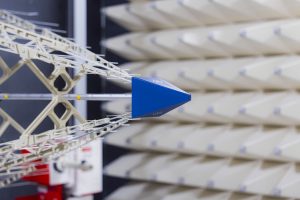
Radiated susceptibility tests expose the device under test (DUT) to an electromagnetic field inside a full or semi-anechoic chamber. A signal generator, RF amplifier, directional coupling and power monitoring, antennas, field probes, cameras, and functional-monitoring instrumentation are used to establish the field and detect abnormal operation.
Use the waveform, modulation, frequency steps and dwell time required by the selected test method. Unmodulated CW exposure can support calibration or diagnostic investigation, but it is not a universal replacement for the prescribed modulated test. Repeatable results also require documented cable routing, loads, firmware and functional monitoring. Specialized pulsed or ultra-wideband research exposures should be identified separately from standardized compliance tests.
5.1 Field Calibration (FC)
In field calibration, the electric field is established and recorded at the DUT location before the DUT is installed. The field probe is then removed, the DUT is placed in the calibrated volume, and the recorded forward-power data are used during exposure. The method is broadly applicable but can be time-consuming and may require separate calibration across multiple antenna and amplifier bands. Probe locations, calibration points and field-setting procedures must follow the selected edition and method; a probe count from one setup should not be generalized to all vehicle or component tests.
5.2 Field Monitoring (FM)
Field monitoring uses a probe as feedback during the test. It can simplify control, but metallic enclosures and large DUTs can perturb the local field and compromise the probe reading. For critical equipment, both calibration and monitoring effects should be considered rather than assuming that one method fully represents the threat environment.
6. Radiated Susceptibility Standards and Test Planning
| Reference | Role in a test plan | What to confirm |
|---|---|---|
| IEC 61000-4-3:2020 | Basic radiated RF immunity method for electrical and electronic equipment. | Product-standard requirements, frequency coverage, modulation, field level, uniformity, orientations and performance criteria. |
| ISO 11452-2 / ISO 11451-2 | Automotive component / complete-vehicle radiated immunity methods. | Component or vehicle scope, selected edition, test arrangement and OEM requirements. |
| Product and product-family immunity standards | Identify which basic tests apply to the product and intended environment. | Applicable edition and national adoption; a historical CISPR 24 reference is not a universal current requirement. |
| RTCA DO-160 Section 20 | Airborne equipment RF susceptibility requirements. | Required edition and installation category; historical DO-160F examples should not be treated as current requirements. |
| MIL-STD-461 RS103 | Military subsystem/equipment radiated susceptibility reference. | Contractual edition, applicability, frequency-dependent levels and installation conditions; confirm test availability and scope separately. |
For converter products, IEC 61000-4-3 is often the basic radiated-immunity method called up by a product or product-family standard. Automotive EMC testing commonly uses ISO 11452-2 for components or ISO 11451-2 for complete vehicles. Aircraft and military equipment require substantially different field-strength profiles and installation-specific categories.
7. Research Examples: What Fails Under Conducted IEMI?
The investigations summarized here are research examples discussed in Reference [1]. They are not Stancer case studies, laboratory capability ratings or universal product test levels.
Conducted-susceptibility testing applies to individual integrated circuits, microcontrollers, operational amplifiers, logic inverters, communication systems, climate-control systems, avionics, cables, GaN half-bridge modules, and complete unmanned systems. Depending on the objective, CW or pulsed signals may be coupled by DPI, BCI, or CDN over frequencies extending from approximately 100 kHz to 2 GHz.
| Target | Signal / method | Frequency range reported | Important finding or objective |
|---|---|---|---|
| Integrated circuits and bandgap/reference devices | Primarily CW or pulse/CW using DPI | 150 kHz–2 GHz across studies | Output-voltage drift, sensitive pins, threshold levels, thermal and ageing effects, and possible permanent damage |
| Microcontrollers | DPI; CW or pulse | 200 kHz–1 GHz typical | Functional errors, threshold mapping, and burn-out morphology |
| Operational amplifiers and logic inverters | CDN or DPI | 1 MHz–1 GHz | Identification of dominant sensitive elements and coupling transfer paths |
| Vehicle infotainment and climate control | Pulse DPI; CW DPI/BCI | 100 kHz–1 GHz | Validation of filters, suppressors, grounding, shielded cables, connectors, and active filtering |
| Avionics and Ethernet cables | DPI or BCI | 10 kHz–1 GHz / 500 kHz–125 MHz | Comparison of cable structures, terminal responses, and system thresholds |
| GaN half-bridge module | CW BCI | 100 kHz–400 MHz | Control-waveform distortion and susceptibility threshold versus injected power |
| Unmanned aerial vehicle | CW BCI | 450–800 MHz | Localization of critical units and IEMI-induced operational failure |
Temperature can significantly change RF susceptibility. For a representative microcontroller, increasing temperature from 25 °C to 75 °C reduced the susceptibility threshold by as much as approximately 10 dBm at 600 MHz. This reversible temperature-related degradation should be distinguished from ageing, which can permanently increase electrical stress and reduce robustness.
8. Converter-Specific Failure Paths
8.1 Control and Gate-Drive Corruption
RF energy can couple into PWM, enable, fault, current-sense, gate-drive, and communication signals. Demodulation and rectification in semiconductor junctions can transform RF into low-frequency offsets or pulses. A distorted gate command may cause false switching, pulse-width error, increased switching loss, shoot-through risk, or loss of regulation.
8.2 Sensor and ADC Misjudgement
Current, voltage, temperature, acceleration, and position sensors often operate at low signal levels. Common-mode RF on sensor wiring can be converted to differential voltage by unequal impedances, asymmetric routing, connector imbalance, or nonlinear input protection. The resulting error may be interpreted as a real process variable and trigger inappropriate control action.
8.3 Communication and Supervisory Failure
CAN, Ethernet, serial links, isolated transceivers, and wireless coexistence interfaces can experience bit errors, resets, command injection, or denial of service. A power converter can remain electrically intact while losing coordination with the host system, creating a system-level safety failure.
8.4 Insulation Breakdown and Thermal Damage
At high field or injected-current levels, the disturbance can create excessive voltage stress, localized heating, repetitive false switching, or semiconductor overcurrent. Temporary malfunction can then progress to insulation breakdown or circuit burn-out.
9. Port Impedance and Equivalent-Circuit Modelling
Susceptibility depends strongly on the impedance presented by the DUT and auxiliary equipment. Assuming ideal 50-Ω terminations can produce unrealistic BCI predictions. One-port S-parameter measurement with a calibrated vector network analyzer can be used to extract DUT impedance from the measured reflection coefficient:
where Z0 is the real reference impedance and S11 is the complex reflection coefficient at the calibrated reference plane. Fixture de-embedding and the chosen common-mode or differential-mode connection determine what impedance is measured. See the Keysight complex-impedance reference. The resulting complex impedance can be fitted to RLC behavioural models and incorporated into SPICE or full-wave/circuit co-simulation. Accurate modelling requires attention to common-mode and differential-mode terminal impedances, cable geometry, return paths, fixture parasitics, injection-probe transfer impedance, saturation, and temperature.
10. Conducted-Immunity Hardening Techniques
| Technique | Purpose | Strength | Limitation / engineering caution |
|---|---|---|---|
| Passive filtering | Attenuate RF at power, signal, and communication interfaces | Directly reduces injected noise and can be optimized by measured transfer function | Parasitics, saturation, fixture effects, and frequency-dependent terminal impedance can create unexpected resonances |
| Active filtering | Sense and cancel induced disturbances | Potentially effective when passive component size or low-frequency attenuation is inadequate | Operating bandwidth, stability, latency, dynamic range, and its own susceptibility must be verified |
| Shielding and shield termination | Reduce coupling into internal wiring and electronics | Effective when shield continuity and low-inductance bonding are maintained | Pigtails, seams, connectors, apertures, and poor chassis bonding can dominate at high frequency |
| Transient suppressors and grounding | Clamp induced voltage and control return-current paths | Useful for system-level protection and connector interfaces | Device capacitance, lead inductance, and clamp current path must be included in the design |
| Cable and harness optimization | Reduce pickup and mode conversion | Twisted, shielded, bifilar, or star-quad configurations can improve robustness | Performance depends on terminal impedance, height above ground, routing, balance, and shield connection |
| Behavioural and full-wave modelling | Predict thresholds, vulnerable paths, and countermeasure performance | Reduces chamber trial-and-error | Requires reliable geometry, material data, frequency-dependent impedance, and validation |
11. Radiated-Susceptibility Investigations
Radiated-susceptibility evaluation applies to components, communication and control boards, battery-management systems, power-conditioning units, vehicles, power grids, and converter-connected cable systems. The engineering objective is to identify sensitive frequencies, critical modules, failure thresholds, coupling paths, and the induced voltages and currents that reach vulnerable terminals.
A power-electronic device may be directly illuminated, but cables are often the dominant receiving structures. A cable-connected system can be represented by a common-mode transmission-line model defined by cable length, diameter, height above ground, left and right terminal impedances, incident electric-field strength, and incidence and polarization angles. Worst-case coupling depends strongly on common-mode terminal impedance and cable height.
12. Radiated-Immunity Hardening
12.1 Cable Filters
Filters at cable interfaces attenuate field-to-cable coupled disturbances before they reach sensitive circuitry. An RC filter used in a battery-management system was effective from approximately 10 to 600 MHz; outside that range, parasitic effects limited performance. Ferrite sheath current filters were also used to suppress common-mode cable current.
12.2 PCB-Level Suppression
PCB strategies include minimizing susceptible loop area, controlling return paths, adding filtering close to connectors and vulnerable IC pins, via fencing, ground stitching, and separating high-field power stages from low-level control and sensing. The effect is frequency dependent: a layout change that improves one resonance may create another unless the complete source-path-load network is considered.
12.3 Shielding Effectiveness
Electric-field shielding effectiveness is defined as:
where Eint and Eext are the electric fields inside and outside the shield. Fully enclosed conductive shielding can provide excellent attenuation, but real converter enclosures include seams, cable penetrations, cooling apertures, displays, joints, and removable covers. These discontinuities can dominate shielding performance. Advanced manufacturing concepts include screen printing, 3D printing, and carbon-fibre meshing, although their practical IEMI performance still requires investigation.
12.4 Cable Coatings and Balanced Structures
Analytical and transmission-line models can evaluate dielectric coatings, shielded and unshielded cables, star-quad configurations, and twisted pairs. These methods are useful for design exploration, but numerical results should be validated against physical measurements before they are used to support a final immunity claim.
13. Why Common-Mode / Differential-Mode Transformation Matters
Mode conversion occurs when common-mode interference becomes differential-mode voltage or current because of imbalance. In a converter, asymmetry can arise from unequal sensor impedances, different line-to-chassis capacitances, connector pin geometry, PCB routing, transformer capacitance, shield termination, and component tolerance. Even a modest common-mode field can therefore create a damaging differential signal at an ADC, comparator, gate driver, or communication receiver.
Accurate measurement and circuit modelling of mode transformation remain important research gaps. Practical immunity engineering should measure both common-mode and differential-mode responses rather than relying on injected current alone.
14. Risk Management and Selection of Test Severity
A complete electromagnetic-risk management process includes five activities: context clarification, stakeholder consultation, risk evaluation, risk treatment, and monitoring/review. EMC work often concentrates on evaluation and treatment while neglecting the operating context and stakeholder-defined consequences. For a converter in an EV, aircraft, grid converter, or medical system, the acceptable response to interference is not defined solely by whether the unit resets; it depends on the resulting system hazard.
| Activity | Questions for the engineering team | Typical output |
|---|---|---|
| Context clarification | Where is the converter installed? Which RF transmitters, cables, fields, and intentional threats are credible? | Threat environment and applicable standards/categories |
| Stakeholder consultation | What constitutes unacceptable behaviour: drift, reset, shutdown, false torque, communication loss, or permanent damage? | Performance criteria and monitored functions |
| Risk evaluation | Which frequencies, ports, modes, temperatures, loads, and orientations create the highest susceptibility? | Vulnerability and consequence ranking |
| Risk treatment | Should the design use filtering, shielding, grounding, cable redesign, software supervision, redundancy, or architecture change? | Hardening plan and verification matrix |
| Monitoring and review | Do hardware revisions, firmware changes, new cables, or updated standards alter the risk? | Configuration control and periodic reassessment |
15. Development and Pre-Compliance Test Workflow
Prepare the converter before booking
Identify intended markets, installation, supply ratings and applicable product or OEM specifications.
Provide production-intent cables, grounding, enclosure, loads, firmware and auxiliary equipment.
Define acceptable output deviation, communication behaviour, protection response and recovery.
Document startup, shutdown, isolation, emergency stop and handling of unexpected converter behaviour.
Phase 1 — Applicable Requirements
Identify the product standard, basic test method, frequency range, level, modulation, dwell time, field uniformity or injection calibration, cable configuration, operating modes, and performance criteria. Regulatory programmes such as FCC certification testing, FCC Part 15 testing, ICES-003 testing, ISED certification, and CE marking principally address market-access requirements; immunity obligations must be identified separately from emission and radio requirements.
Phase 2 — Vulnerability Mapping
List every external cable, shield termination, control input, sensor, communication port, isolation barrier, gate driver, and protection input. Estimate which structures behave as receiving antennas and where common-mode to differential-mode conversion can occur.
Phase 3 — Bench Injection and Diagnostics
Use DPI, CDN, or BCI where technically appropriate. Measure injected current or forward power, terminal voltage, S-parameters, common-mode current, control waveforms, sensor output, switching-node behaviour, temperature, and functional status. Record the first deviation and permanent-damage threshold separately.
Phase 4 — Pre-Compliance EMC Testing
Perform pre-compliance EMC testing with production-intent cable lengths, grounding, firmware, load, enclosure, auxiliary equipment, and operating modes. Sweep slowly near resonances and known communication frequencies. Test minimum and maximum input voltage, representative load points, start-up, shutdown, fault recovery, and communication activity.
Phase 5 — Accredited Testing and Product Compliance
Complete formal testing at an accredited EMC testing laboratory using the required method and calibrated equipment. Maintain configuration control between the tested sample and production product. Where the converter includes a radio, coordinate immunity work with radio frequency testing, wireless device certification, FCC certification testing, ISED certification support, and RED certification testing as applicable.
16. Design Checklist for Converter Immunity
- Keep high-dV/dt power nodes physically separated from ADC, sensor, clock, reset, communication, and protection circuitry.
- Minimize gate-drive and commutation-loop area and provide a low-inductance return path.
- Place RF filtering at the interface where a cable enters the enclosure, not deep inside the PCB after a long unfiltered trace.
- Control common-mode impedance to chassis and avoid accidental resonant return paths through heat sinks and mounting structures.
- Use balanced routing and matched input filtering to reduce common-mode to differential-mode conversion.
- Terminate cable shields with low-inductance, preferably 360-degree connections where product architecture permits.
- Avoid long shield pigtails at VHF and UHF frequencies.
- Characterize ferrites, common-mode chokes, capacitors, and filters over the actual frequency and bias range.
- Include probe and fixture nonlinearity, current-probe saturation, temperature, and terminal impedance in BCI analysis.
- Test the product at elevated and low temperature when component susceptibility is temperature dependent.
- Monitor control signals, gate voltage, output regulation, communications, and protection status continuously during exposure.
- Distinguish performance degradation, recoverable malfunction, reset, latch-up, and permanent damage in the test report.
- Repeat testing after enclosure, cable, PCB, firmware, or connector changes.
17. Related Compliance Programmes for Commercial Products
Converter immunity is often only one part of a broader approval programme. Stancer Testing-Lab supports EMC compliance testing, electromagnetic compatibility testing, EMI testing services, and product compliance testing for industrial, automotive, wireless, medical, and multimedia products. Products containing intentional radiators may also require an RF testing lab for FCC Part 15 testing, ISED certification support, and wireless device certification.
For the European market, immunity results may form part of the technical evidence supporting CE marking. Depending on the product, the applicable framework may include the EMC Directive, Radio Equipment Directive, machinery or safety legislation, and product-specific standards. Medical converters and powered medical devices may require medical device EMC testing and IEC 60601-1-2 testing, including radiated RF immunity, conducted RF immunity, electrostatic discharge, EFT/burst and surge testing, magnetic field immunity, and voltage dips and short interruptions testing, as applicable. Electrostatic events should be evaluated through dedicated ESD testing rather than assumed from RF susceptibility results.
18. Challenges and Future Research
18.1 Wideband Characterization of Filtering Components
Filters, common-mode chokes, ferrites, and feedthrough structures must be characterized under realistic DC current, voltage, temperature, and common-mode/differential-mode conditions. Test fixtures for non-coaxial high-power components require careful calibration and de-embedding, particularly at high frequency.
18.2 High-Frequency Impedance Extraction
Reliable immunity prediction requires in-circuit impedance measurement of converters, cables, power modules, motors, filters, and multi-phase chokes. Voltage-current, capacitive-coupling, and inductive two-probe methods each offer advantages, but their usable frequency range and uncertainty must be established.
18.3 Shielding Design with Real Openings and Manufacturing Tolerances
Analytical and numerical shielding models frequently neglect thickness variation at bends, mesh-density variation, seams, joints, heat-dissipation holes, and connection gaps. Future design methods need manufacturing-aware models and adequate design margin.
18.4 Quantitative Mode-Conversion Models
Common-mode/differential-mode transformation must be included in circuit and full-wave models to predict the actual voltage and current reaching sensitive terminals.
18.5 Converter-Specific IEMI Risk Management
Risk frameworks developed for power grids or railway infrastructure may not transfer directly to mobile and embedded power-electronic equipment. Converter-specific strategies must account for mobility, field exposure, threshold variability, architecture, mission, and consequence of failure.
19. Frequently Asked Questions
What is the difference between conducted immunity and radiated immunity testing?
Conducted immunity injects RF disturbance into connected cables or ports using a CDN, BCI probe, or direct injection network. Radiated immunity exposes the complete product to a calibrated or monitored electromagnetic field using an antenna in a shielded chamber. A converter may require both because a field can couple through space while cables transfer the resulting current and voltage to internal electronics.
Which standard is commonly used for conducted RF immunity?
IEC 61000-4-6 is a widely used basic test method for conducted disturbances induced by RF fields. Product and product-family standards define whether it applies, the frequency range, level, modulation, dwell time, cable setup, and performance criteria.
Which standard is commonly used for radiated RF immunity?
IEC 61000-4-3 is a widely used basic radiated-immunity method. Automotive components commonly use ISO 11452-2, complete vehicles use ISO 11451-2, airborne equipment uses DO-160 categories, and military equipment may use MIL-STD-461 RS103.
Why are power-electronic converters vulnerable to RF interference?
Converters combine long cables, high-impedance sensor inputs, fast control electronics, nonlinear semiconductor junctions, switching nodes, isolation barriers, and communication links. RF can couple onto cables, convert from common mode to differential mode, and be rectified or demodulated inside ICs, causing offsets, false commands, resets, or damage.
Can passing emissions testing prove that a converter is immune?
No. Emissions and immunity evaluate different directions of electromagnetic interaction. A low-emission product can still have vulnerable control, sensor, cable, or enclosure paths. Both emission and immunity requirements must be evaluated.
What should I prepare for power electronics immunity testing?
Bring a representative converter, production-intent cables, loads and auxiliary equipment, firmware details, a safe operating procedure and a list of functions to monitor. Agree on the applicable standards, test conditions and performance criteria before testing. Stancer supports clients targeting international markets; contact the team to confirm the applicable methods and accredited scope for your project.
Power-electronics immunity testing support: Stancer Testing-Lab provides EMC testing, radiated immunity testing, conducted immunity testing, ESD testing, RF testing, and CE marking and global product-compliance support for industrial converters, EV power electronics, battery systems, renewable-energy equipment, medical devices, and wireless products.
Conclusion
EMC immunity in power-electronic converters is a system problem governed by source amplitude, frequency, coupling path, cable geometry, terminal impedance, common-mode/differential-mode conversion, semiconductor nonlinearity, control architecture, temperature, shielding, and filtering. Susceptible behaviour can occur from the kilohertz range to gigahertz frequencies and can progress from small output drift to permanent physical damage.
The most reliable strategy is to combine risk-based requirement selection, component and port characterization, representative pre-compliance testing, calibrated conducted and radiated exposure, quantitative modelling, and validated hardening. Filters and shields should not be added as isolated remedies; they must be designed as part of the complete converter, cable, enclosure, and control system.
References
- H. Jie et al., “A review of intentional electromagnetic interference in power electronics: Conducted and radiated susceptibility,” IET Power Electronics, vol. 17, pp. 1487–1506, 2024. doi: 10.1049/pel2.12685. Research examples in this guide draw on this review.
- IEC 61000-4-6, Electromagnetic compatibility (EMC) — Part 4-6: Testing and measurement techniques — Immunity to conducted disturbances, induced by radio-frequency fields.
- IEC 61000-4-3, Electromagnetic compatibility (EMC) — Part 4-3: Testing and measurement techniques — Radiated, radio-frequency, electromagnetic field immunity test.
- EN 62132-1, EN 62132-3, and EN 62132-4, Integrated circuits — Measurement of electromagnetic immunity, 150 kHz to 1 GHz.
- ISO 11451-2 and ISO 11451-4, Road vehicles — Vehicle test methods for electrical disturbances from narrowband radiated electromagnetic energy.
- ISO 11452-2 and ISO 11452-4, Road vehicles — Component test methods for electrical disturbances from narrowband radiated electromagnetic energy.
- SAE J1113-4, Immunity to radiated electromagnetic fields — Bulk current injection method.
- SAE J551-16 and SAE J1113-28, electromagnetic-immunity measurement procedures for vehicles, boats, machines, and components.
- DO-160F, Environmental Conditions and Test Procedures for Airborne Equipment.
- MIL-STD-461G, Requirements for the Control of Electromagnetic Interference Characteristics of Subsystems and Equipment, including CS114 and RS103.
- CISPR 24, Information technology equipment — Immunity characteristics — Limits and methods of measurement.
- CISPR 14-2, Electromagnetic compatibility — Requirements for household appliances, electric tools and similar apparatus — Immunity.
- EN 61547, Equipment for general lighting purposes — EMC immunity requirements.