

Conducted Immunity Testing (CI)
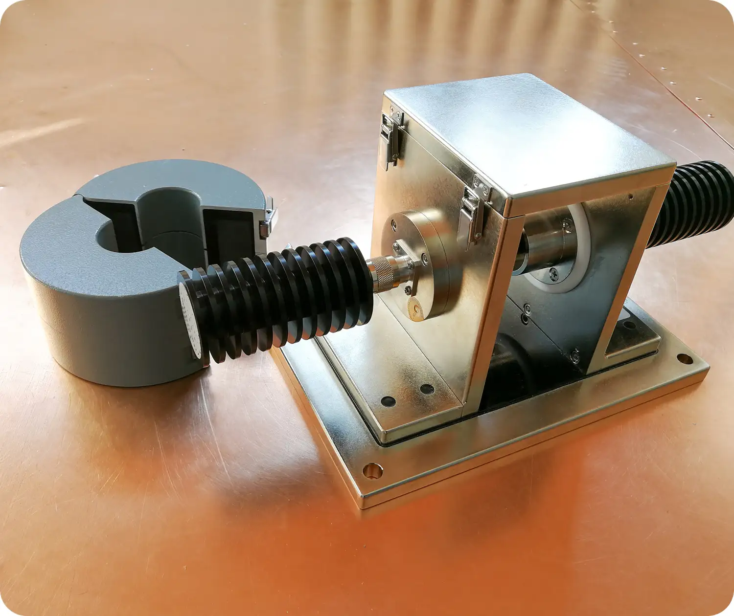
Conducted Immunity Testing
Conducted RF immunity testing evaluates how equipment performs when radio-frequency disturbances are coupled onto its power, signal or communication cables. Engineers monitor the product for resets, data errors, incorrect readings and other changes in operation.
Stancer Testing-Lab works with manufacturers and product development teams to select the appropriate injection method, define operating modes and monitor the functions relevant to the application. Testing can support a formal EMC program or a focused pre-compliance investigation.
What Conducted RF Immunity Testing Helps You Assess
- Evaluate specified functions during RF disturbances on connected cables.
- Identify susceptible ports, operating modes and frequencies.
- Investigate resets, communication errors and sensor disturbances.
- Compare filters, grounding, shielding and cable changes.
- Prepare evidence for the applicable product immunity requirements.
Results apply to the tested configuration and agreed performance criteria. Testing does not guarantee immunity to every electrical disturbance.
Conducted RF Immunity: From Cable Setup to Results
Frequency Coverage
IEC conducted RF programs typically cover 150 kHz–80 MHz. Extended testing up to 230 MHz is subject to confirmation of the method, setup and project requirements.Test Levels
Voltage-based capability includes levels up to 40 V, subject to the selected coupling arrangement and frequency. Automotive BCI levels are specified separately in terms of injection current.Performance Monitoring
Relevant functions are observed against agreed acceptance criteria, with disturbances and recovery behaviour documented.How the Test Progresses
- PlanDefine ports and acceptance criteria.
- CalibrateEstablish the specified injection level.
- InjectApply the specified RF test sequence.
- MonitorObserve the agreed product functions.
- ReportDocument conditions and results.
Controlled Injection and Monitoring
We select coupling/decoupling networks (CDNs), EM clamps or current-injection arrangements according to the applicable method and cable configuration. Power and communication connections are reviewed so the test setup reflects the product's intended operation. Before exposure, the injection arrangement is calibrated using the specified procedure. The test plan defines frequency range, level, modulation, frequency steps, dwell time and the ports to be evaluated. Cable routing, grounding and auxiliary equipment are documented. During the sweep, the product operates in the agreed modes while its relevant functions are monitored. We record observed disturbances, affected frequencies and recovery behaviour and compare them with the specified acceptance criteria.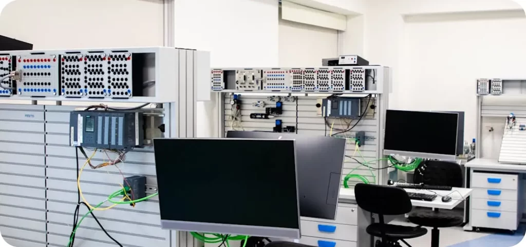
Applicable Standards
IEC 61000-4-6 defines a conducted RF immunity method for electrical and electronic equipment. Its principal frequency range is 150 kHz to 80 MHz. The applicable product or generic standard determines the required level, port selection and performance criteria. For medical electrical equipment, conducted RF immunity can form part of the IEC 60601-1-2 program, with monitoring appropriate to basic safety and essential performance. Explore our medical device EMC testing service. Automotive component bulk current injection (BCI) under ISO 11452-4 evaluates harness susceptibility using its own calibration and test procedures. It is not interchangeable with an IEC voltage-level test. See our automotive EMC testing service. The applicable edition, clauses and accredited coverage are confirmed against our scope of accreditation and the agreed test plan. For multimedia equipment, CISPR 35 / EN 55035 identifies conducted RF immunity requirements according to the applicable ports and functions.Prepare Your Product
Provide the requested standard or customer specification, electrical ratings, target markets, operating modes and port list. Include cable types, lengths, shielding, connectors, communication equipment and representative loads. Define the monitored functions, acceptable behaviour during exposure and any permitted recovery actions. Bring the firmware, accessories and equipment needed to operate and monitor the product. Complete our EMC & RF Client Information Sheet and upload it through the contact form.Conducted RF Immunity Testing FAQs
How does conducted immunity differ from conducted emissions?
Is IEC 61000-4-6 the same as automotive BCI testing?
Does this test also cover surge, EFT or voltage dips?
Can you investigate a conducted immunity failure?
Plan your testing
Let’s move your product toward market.
Tell us about your product, testing needs, and target markets. Our technical team will help define the scope and prepare a tailored quotation.