
All about EMI filters
Active EMI Filters for Power Converters: Smaller, Lighter, and Smarter EMC Design
Power converters are the quiet workhorses behind modern electronics. They step voltage up, step voltage down, convert AC to DC, drive motors, charge batteries, and manage energy in everything from smartphones and medical devices to industrial automation, renewable energy systems, electric vehicles, and aerospace electronics.
They also create one of the most persistent challenges in EMC testing: electromagnetic interference. The same high-speed switching that makes modern converters compact and efficient can generate conducted emissions, radiated emissions, common-mode currents, and broadband noise that may affect nearby electronics or cause regulatory failures.
Why EMI Is Such a Persistent Problem in Power Converters
A power converter does not produce EMI because it is poorly designed. EMI is a natural consequence of rapid energy conversion. Every time a MOSFET, IGBT, SiC device, or GaN transistor switches, current and voltage change rapidly. These fast transitions create high di/dt and high dv/dt, which excite parasitic inductance, capacitance, cables, ground structures, and enclosure paths.
In practical terms, the converter becomes both a power system and an RF noise source. The switching frequency may be only tens of kilohertz or a few megahertz, but the harmonics can extend far into the frequency ranges assessed during conducted emissions testing and radiated emissions testing.
Traditionally, engineers control this noise with passive EMI filters made from inductors, capacitors, ferrites, common-mode chokes, and damping networks. These components work, but they can become large, heavy, expensive, and difficult to package, especially in high-power-density converters. In some designs, the EMI filter can occupy a surprisingly large fraction of the converter volume.
Engineering insight: The EMI filter is often treated as an accessory added near the end of the design. In reality, it is part of the power converter architecture. Its performance depends on source impedance, load impedance, PCB layout, grounding, parasitic coupling, enclosure bonding, and cable configuration.
What Is an Active EMI Filter?
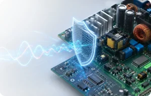
An Active EMI Filter, often abbreviated as AEF, is an electronic circuit that senses unwanted noise and injects a corrective signal to reduce that noise. Instead of relying only on large passive inductors and capacitors, the AEF uses active circuitry to cancel part of the disturbance.
The idea is similar in spirit to active noise cancellation in audio systems. A microphone senses unwanted sound, electronics process the signal, and a speaker generates an opposing waveform. In an active EMI filter, the “sound” is electrical noise. The sensing circuit detects EMI, the processing stage conditions it, and the injection stage introduces a cancellation voltage or current into the system.
AEFs are especially attractive in power electronics because they can reduce the size and weight of passive filters. This matters in electric vehicles, aircraft, industrial drives, compact power supplies, renewable energy converters, robotics, medical equipment, and other systems where volume, weight, and thermal performance are tightly constrained.
Smaller Filters
AEFs can reduce the required size of passive inductors and capacitors, especially where low-frequency attenuation would otherwise require bulky components.
Adaptive Control
Active circuits can be tuned for changing converter conditions, operating modes, and load profiles.
Higher Power Density
By reducing passive filter volume, AEFs support compact converter designs with improved system integration.
The Three Building Blocks of an Active EMI Filter
Although AEF implementations vary, most active EMI filters include three functional blocks: sensing, processing, and injection.
| AEF Block | Function | Design Considerations |
|---|---|---|
| Noise-sensing circuit | Detects the unwanted EMI voltage or current. | Must sense the correct noise mode without disturbing normal converter operation. |
| Noise-processing circuit | Amplifies, conditions, phase-adjusts, or digitally processes the sensed signal. | Bandwidth, phase response, delay, gain stability, and noise floor are critical. |
| Noise-injection circuit | Injects a cancellation voltage or current back into the system. | Must couple the cancellation signal effectively without creating instability or new emissions. |
Noise Sensing
The sensing stage may measure noise voltage, noise current, or a combination of both. For common-mode noise, sensing often involves detecting the voltage or current that appears simultaneously on multiple conductors relative to a reference such as chassis or earth. For differential-mode noise, the focus is the disturbance between two conductors, such as positive and negative DC bus lines.
Noise Processing
The processing stage must generate the correct amplitude and phase relationship for cancellation. This is where AEF design becomes demanding. A cancellation signal that is too small will not provide enough attenuation. A signal with the wrong phase can make the EMI worse. A feedback design with poor phase margin can become unstable.
Noise Injection
The injection stage introduces the cancellation signal into the converter system. Depending on the design, it may inject a voltage in series with the noise path or a current in parallel with it. The injection network must be designed carefully because its parasitic impedance can strongly influence the final attenuation.
Common-Mode and Differential-Mode EMI
Active EMI filters can target common-mode noise, differential-mode noise, or both. The distinction matters because the current paths, filter topology, sensing method, and injection strategy are different.
| Noise Type | How It Flows | Why It Matters | Typical AEF Strategy |
|---|---|---|---|
| Common-mode noise | Flows in the same direction on multiple conductors and returns through parasitic capacitance, chassis, earth, or the environment. | Often responsible for cable radiation, enclosure coupling, and failures during radiated emissions testing. | Sense common-mode voltage/current and inject a cancellation signal relative to chassis or reference ground. |
| Differential-mode noise | Flows between conductors, such as line-to-line or DC bus positive-to-negative. | Often dominates conducted emissions on power lines and can affect power quality. | Sense line-to-line noise and inject series or parallel cancellation into the differential path. |
In many real converters, the two modes are coupled. A layout issue that starts as differential-mode switching noise can convert into common-mode current through parasitic capacitance to heat sinks, chassis, shields, or cables. This is why practical EMI troubleshooting often requires both measurement and engineering interpretation.
Feedforward Versus Feedback Active EMI Filters
AEFs are commonly described using two control approaches: feedforward and feedback. Both can work, but they behave differently and require different design tradeoffs.
Feedforward AEF
A feedforward active EMI filter senses the noise before it reaches the protected port and injects a cancellation signal derived from that sensed noise. The concept is direct and can be relatively fast because the signal path does not depend on measuring the residual output after cancellation.
The challenge is sensitivity to component tolerances, phase shift, propagation delay, and changes in operating conditions. If the relationship between the sensed noise and the injected cancellation signal changes, attenuation may degrade.
Feedback AEF
A feedback active EMI filter senses the remaining noise after filtering and adjusts the injected signal to reduce it. This can make the system more robust against parameter variation, but it also introduces classical feedback-control concerns: loop gain, bandwidth, phase margin, stability, and compensation.
Laboratory observation: A feedback AEF may perform very well in one operating condition but become marginal when load, temperature, cable impedance, or converter mode changes. Stability analysis and testing across realistic operating states are essential before relying on the AEF for compliance margin.
| Control Method | Advantages | Challenges | Best Fit |
|---|---|---|---|
| Feedforward | Fast, conceptually simple, useful where noise path is predictable. | Sensitive to tolerances, phase error, and changing impedance. | Converters with stable noise characteristics and well-controlled layout. |
| Feedback | Can adapt to residual noise and component variation. | Requires loop-stability design, compensation, and careful validation. | Systems where operating conditions vary and residual noise monitoring is practical. |
Where Active EMI Filters Are Used
AEFs are most useful where passive filtering becomes too large, too heavy, or too difficult to integrate. They are not a universal replacement for passive EMI filters, but they can be powerful when used as part of a coordinated EMC strategy.
DC-DC Converters
DC-DC converters appear in battery systems, embedded electronics, industrial controls, telecom equipment, robotics, automotive modules, and medical devices. Active EMI filters can reduce conducted noise on DC input or output lines, especially when converter size is limited and passive inductors are difficult to package.
AC-DC Power Supplies
AC-DC converters must manage switching noise while meeting power-line emission limits, safety requirements, and sometimes harmonic and flicker testing requirements. AEFs can support compact designs, but safety isolation, leakage current, surge behavior, and regulatory constraints must be considered carefully.
Inverters and Motor Drives
Inverters used in electric vehicles, industrial motor drives, renewable energy systems, and traction applications generate strong common-mode noise because of high dv/dt switching and parasitic capacitance between power devices, heat sinks, motors, and cables. AEFs can help reduce common-mode current, but they must be validated under real switching conditions and cable configurations.
Electric Vehicles and High-Power Electronics
EV powertrains, onboard chargers, DC-DC converters, and battery management systems operate in dense electromagnetic environments. These systems may need to satisfy automotive requirements such as CISPR 25, CISPR 12, ISO 11452, ISO 7637, ISO 10605, and UNECE R10. For manufacturers working in this space, early automotive EMC testing and pre-compliance evaluation are critical.
Benefits of Active EMI Filters
| Benefit | Why It Matters |
|---|---|
| Reduced size and weight | AEFs can reduce the required value or physical size of passive inductors and capacitors, supporting higher power density. |
| Improved attenuation in targeted bands | Active cancellation can be tuned to problematic frequency ranges identified during pre-compliance testing. |
| Design flexibility | AEFs can be adapted to different operating modes, loads, and converter conditions. |
| Potential cost optimization | Reducing large magnetic components may offset the added cost of active circuitry in some applications. |
| Better integration in compact systems | AEFs can help when mechanical constraints make traditional passive filters impractical. |
Challenges and Design Risks
Active EMI filters introduce new design considerations. They are not passive components that can simply be added to a schematic and expected to work. Their success depends on control-loop behavior, sensing accuracy, injection effectiveness, PCB layout, parasitic coupling, and the converter operating envelope.
Stability
Feedback AEFs require careful stability analysis. Loop gain, phase delay, amplifier bandwidth, injection impedance, and load variation can all influence stability. A design that is stable on the bench may behave differently when connected to the real harness, motor cable, LISN, or mains network used during formal testing.
Power Loss and Auxiliary Supply Requirements
AEFs consume some power because they use active components. In many systems this loss is small compared with converter output power, but it still matters in battery-powered equipment, high-efficiency converters, and thermally constrained designs.
Noise Floor and Saturation
The active circuit must have sufficient dynamic range. If the sensed noise is too small, the filter may be limited by its own noise floor. If the disturbance is too large, the amplifier or injection stage may saturate and lose cancellation capability.
EMC of the AEF Itself
An active filter is still an electronic circuit. Poor layout, unstable control, or noisy auxiliary supplies can create new emissions. The AEF must therefore be evaluated as part of the complete converter, not as an isolated block.
Design caution: An active EMI filter can reduce EMI, but it can also become an EMI source if the sensing, processing, injection, grounding, and layout are not treated as an integrated RF design problem.
Passive, Active, and Hybrid EMI Filtering
In practice, many successful designs use a hybrid approach. Passive components handle high-frequency attenuation, surge robustness, safety-related requirements, and broadband damping. Active circuits reduce selected noise components or provide low-frequency attenuation without requiring large magnetics.
| Filter Strategy | Strengths | Limitations |
|---|---|---|
| Passive EMI filter | Robust, simple, well understood, no active control required. | Can be large, heavy, and sensitive to source/load impedance interactions. |
| Active EMI filter | Can reduce size, target specific noise modes, and adapt to operating conditions. | Requires power, stability analysis, control design, and careful validation. |
| Hybrid EMI filter | Combines passive robustness with active cancellation for compact high-performance filtering. | More complex than purely passive filtering and requires system-level optimization. |
Design-for-Compliance Considerations
AEF success depends heavily on the underlying converter design. If the layout has excessive loop area, poor grounding, long noisy traces, uncontrolled return paths, and cable coupling, the active filter may be forced to solve problems that should have been addressed at the source.
Practical AEF Design Checklist
- Identify whether the dominant noise is common-mode, differential-mode, or mixed-mode.
- Measure the baseline converter noise before selecting the active filter topology.
- Minimize switching loop areas before relying on active cancellation.
- Place sensing and injection points based on real noise-current paths.
- Validate stability across input voltage, load range, temperature, cable configurations, and operating modes.
- Check AEF performance with the same LISN, harness, grounding, and enclosure conditions used during compliance testing.
- Confirm that the AEF does not introduce new emissions or immunity weaknesses.
- Document assumptions, test modes, and design limits for future regulatory or customer review.
How AEFs Fit Into EMC Testing
Active EMI filters are design tools, but their effectiveness must be proven through measurement. A converter may show excellent attenuation in a simulation and still fail when connected to a real cable, LISN, enclosure, or load. Formal and pre-compliance testing remain essential.
A typical EMC validation path for a converter using an AEF may include:
- Baseline conducted emissions testing with the AEF disabled or bypassed, where safe and practical.
- Conducted emissions testing with the AEF enabled across load and input-voltage conditions.
- Radiated emissions testing with representative cables, enclosure, grounding, and operating modes.
- Immunity testing to confirm that external disturbances do not destabilize the active filter.
- Thermal and long-duration operation checks to verify stable cancellation over time.
- Documentation of test setup, AEF state, firmware mode, and operating conditions.
For products that include wireless communication or intentional RF transmitters, AEF validation should also be coordinated with RF performance testing to ensure the filter does not affect radio performance or introduce unwanted spurious emissions.
When Should Engineers Consider an Active EMI Filter?
An AEF is worth considering when a passive EMI filter becomes too large, too heavy, too expensive, or insufficiently effective in the target frequency range. It is also attractive when the converter operates across changing conditions that make fixed passive filtering difficult to optimize.
However, an AEF should not be the first excuse to ignore good EMC design. The best results usually come from reducing noise at the source, controlling propagation paths, and then using active filtering where it provides clear system-level benefit.
| Good Candidate for AEF | Less Suitable for AEF |
|---|---|
| High-power-density converter with limited space for magnetics. | Low-cost design where passive filtering already meets limits with margin. |
| System where common-mode noise dominates and passive choke size is problematic. | Design with severe layout problems that should be corrected first. |
| EV, aerospace, industrial, or medical systems where weight and volume are critical. | Products where added control complexity cannot be validated or maintained. |
| Converter with well-characterized noise paths and stable operating modes. | Systems with poorly understood cable, enclosure, or load conditions. |
Stancer Testing-Lab Support for Power Converter EMC
Stancer Testing-Lab supports manufacturers developing power converters, motor drives, battery systems, industrial electronics, automotive modules, medical electronics, and wireless products. Our team can help evaluate conducted and radiated emissions, identify dominant noise paths, compare passive and active filtering strategies, and support formal compliance planning.
Our capabilities include EMC testing, conducted emissions testing, radiated emissions testing, conducted immunity testing, radiated immunity testing, ESD testing, harmonic and flicker testing, and support for CE marking and global product compliance.
Frequently Asked Questions About Active EMI Filters
What is an active EMI filter?
An active EMI filter is an electronic circuit that senses unwanted electromagnetic noise and injects a cancellation signal to reduce that noise. It is often used to reduce the size or improve the performance of passive EMI filters in power converters.
How does an active EMI filter work?
An AEF typically uses a sensing circuit to detect noise, a processing stage to condition the signal, and an injection circuit to introduce an opposing signal that cancels part of the EMI.
Can active EMI filters replace passive EMI filters?
Sometimes they can reduce the required passive filter size, but they rarely eliminate passive filtering entirely. Many practical designs use a hybrid approach combining passive and active filtering.
What is the difference between common-mode and differential-mode EMI?
Common-mode EMI flows in the same direction on multiple conductors and returns through parasitic paths. Differential-mode EMI flows between conductors. Each requires different sensing, filtering, and mitigation strategies.
Are active EMI filters useful for electric vehicles?
Yes. EV power electronics often require compact, lightweight EMI solutions. AEFs can be useful in onboard chargers, DC-DC converters, inverters, and high-voltage power systems when properly designed and validated.
What are the main risks of active EMI filters?
The main risks include control-loop instability, amplifier saturation, added power loss, sensitivity to layout, and the possibility that the active circuit itself introduces new noise.
Do active EMI filters require EMC testing?
Yes. Their performance must be verified through conducted emissions, radiated emissions, and immunity testing under realistic operating conditions.
What is a hybrid EMI filter?
A hybrid EMI filter combines passive components with an active cancellation circuit. This approach can provide strong attenuation while reducing the size of bulky passive components.
When should a design team consider using an AEF?
An AEF should be considered when passive filters become too large, too heavy, or insufficiently effective, especially in high-power-density converters where volume and weight are critical.
Can an AEF fix a poor PCB layout?
No. An active EMI filter should not be used to compensate for fundamental layout problems. Hot-loop area, return paths, grounding, and cable coupling should be corrected first.
How does feedback control affect AEF stability?
Feedback AEFs require adequate phase margin and gain margin. If delay, impedance variation, or amplifier limits are not managed, the filter can oscillate or amplify noise instead of reducing it.
Are AEFs suitable for medical devices?
They can be, but medical devices require careful EMC, safety, risk management, and documentation. Any active filter used in medical equipment should be validated under applicable standards such as IEC 60601-1-2.
Can AEFs help reduce conducted emissions?
Yes. Many AEFs are designed specifically to reduce conducted common-mode or differential-mode noise on power lines.
Can AEFs help reduce radiated emissions?
Indirectly, yes. By reducing common-mode current on cables and conductors, an AEF can reduce radiated emissions caused by those cables acting as antennas.
How can Stancer Testing-Lab help with active EMI filter validation?
Stancer Testing-Lab can support pre-compliance testing, conducted and radiated emissions evaluation, immunity testing, troubleshooting, and regulatory planning for power converters using passive, active, or hybrid EMI filters.
References and Useful External Resources
1. IEC – International Electrotechnical Commission: https://www.iec.ch/
2. CISPR standards information through IEC: IEC and CISPR standards
3. IEEE Xplore – Power electronics and active EMI filter research: https://ieeexplore.ieee.org/
4. FCC Equipment Authorization: https://www.fcc.gov/oet/ea
5. ISED Canada – Devices and equipment: ISED spectrum management