

IEC 61800-3 Explained: EMC Compliance for Variable Speed Drives and Power Drive Systems
IEC 61800-3 EMC Requirements for Variable Frequency Drives and Power Drive Systems
Variable Frequency Drives (VFDs), Adjustable Speed Drives (ASDs), and Power Drive Systems (PDSs) are now central to modern industry. They are used in manufacturing plants, water treatment facilities, mining operations, HVAC systems, renewable energy installations, and oil and gas infrastructure. Their value is practical and measurable: better process control, lower energy consumption, improved productivity, and longer equipment life. For products that include wireless modules or communication functions, RF testing may also be required alongside EMC evaluation.
By controlling motor speed and torque with precision, modern drive systems help operators reduce operating costs and improve reliability. However, the same power electronics that make these systems efficient can also create significant electromagnetic compatibility (EMC) challenges.
High-speed switching devices such as IGBTs and power MOSFETs are essential building blocks in modern Power Drive Systems. They provide excellent efficiency and control, but they can also generate electromagnetic interference (EMI). Without proper design, mitigation, installation practices, and EMC testing, these disturbances may affect communication networks, sensors, automation equipment, control systems, and nearby electronic devices.
IEC 61800-3 addresses these issues by defining EMC requirements, emission limits, immunity criteria, installation considerations, and test methods for adjustable speed electrical power drive systems. For many manufacturers and system integrators, compliance with IEC 61800-3 is an important step toward CE marking, EMC certification, product certification, and global market access.
This article explains the role of IEC 61800-3, the classification of Power Drive Systems, the most common EMC problems found in VFD installations, and the practical engineering steps that help manufacturers, integrators, and testing laboratories achieve reliable compliance.
What Is IEC 61800-3?
IEC 61800-3 is the international product standard that defines EMC requirements for adjustable speed electrical power drive systems. It helps ensure that a drive system can function properly in its intended electromagnetic environment while limiting the electromagnetic disturbances it introduces into that environment.
The standard covers emission limits, immunity requirements, test methods, installation guidance, and classification criteria. In Europe, EN 61800-3 is commonly used to demonstrate compliance with the EMC Directive for relevant drive systems.
Understanding Power Drive Systems
A common misconception is that the Variable Frequency Drive alone is the complete drive system. IEC 61800-3 uses a broader concept: the Power Drive System, or PDS.
A typical PDS includes control electronics, power conversion electronics, the motor, encoder or feedback devices, and interconnecting cables. The driven machine itself is generally not considered part of the PDS.
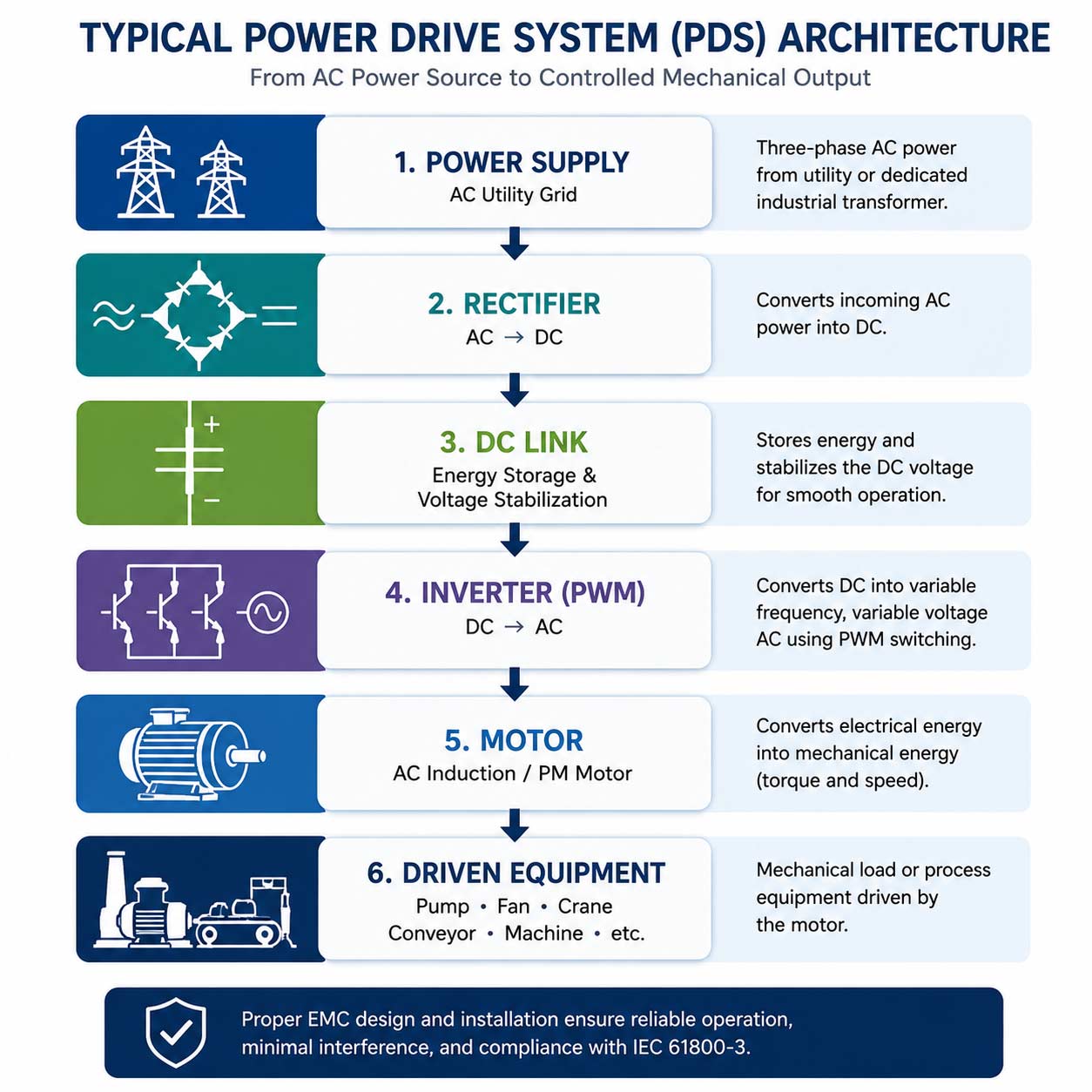
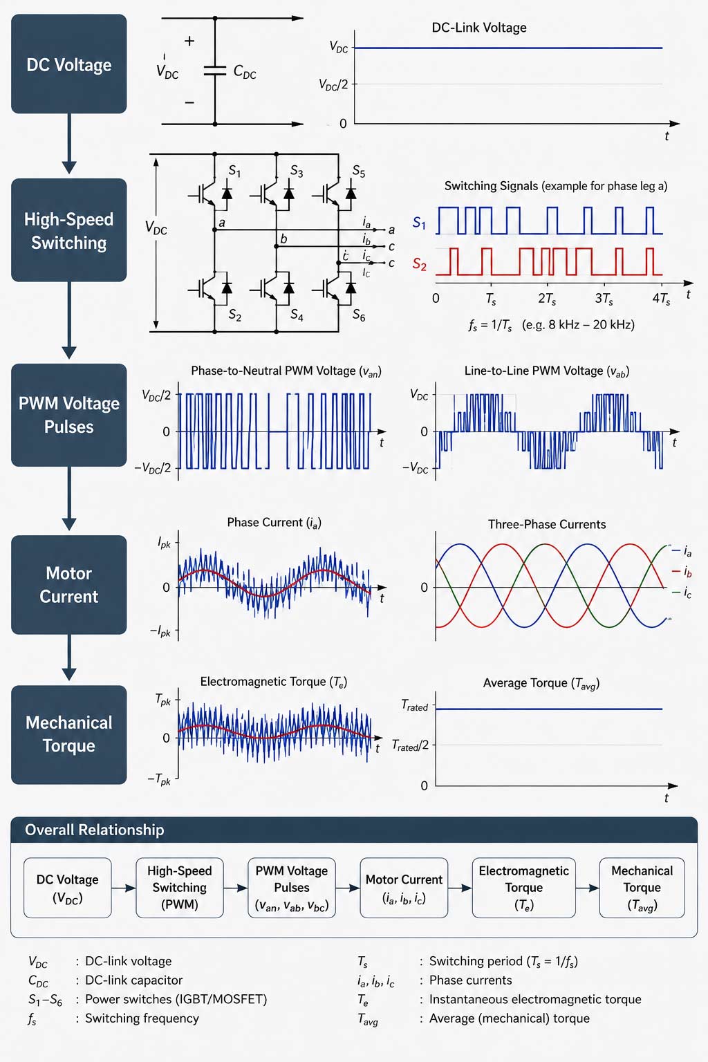
The rectifier converts incoming AC power into DC. The DC link acts as an energy buffer, while the inverter generates a controlled AC waveform to drive the motor. This conversion process is efficient and flexible, but the rapid switching inside the inverter is also the source of many EMC problems.
Why EMC Matters for Variable Speed Drives
The rapid switching action inside modern drives generates high-frequency electrical noise. Large industrial drives often switch in the range of 1 kHz to 20 kHz, while smaller drives may switch at 50 kHz or higher. These switching frequencies improve motor control, but they also create high-frequency spectral components that can travel through power cables, motor cables, grounding systems, cable shields, and nearby metallic structures.
Without proper EMC design, these disturbances may lead to PLC malfunctions, sensor errors, communication failures, nuisance tripping, data corruption, premature motor bearing failures, and unexpected downtime. In automated production environments, the economic impact can be substantial.
EMC Definition
Electromagnetic compatibility is the ability of equipment to function satisfactorily in its electromagnetic environment without introducing intolerable electromagnetic disturbances to anything in that environment.
In practice, EMC has two sides. The first is emissions control: the drive must not emit excessive electromagnetic interference. The second is immunity: the drive must continue to operate correctly when exposed to electromagnetic disturbances. IEC 61800-3 addresses both aspects.
IEC 61800-3 Environmental Classification
One of the most important parts of IEC 61800-3 is the distinction between installation environments. The standard defines two primary environments.
IEC 61800-3 Categories
IEC 61800-3 further divides power drive systems into four categories. These categories help define where a system may be used and what level of EMC control is expected.
Typical Applications Covered by IEC 61800-3
IEC 61800-3 applies to a wide range of industrial applications, including pumps, fans, compressors, conveyors, cranes, hoists, robotics, machine tools, cement plants, rolling mills, extrusion systems, drilling equipment, material handling systems, and marine propulsion systems.
Many modern facilities operate dozens or hundreds of drives at the same time. As the number of drives increases, the electromagnetic environment becomes more complex, and system-level EMC engineering becomes more important.
EMC Challenges Associated with Variable Frequency Drives
Power electronic switching creates two major categories of electromagnetic disturbance: differential-mode noise and common-mode noise.
Differential-Mode Noise
Differential-mode noise circulates within the intended current-carrying conductors. Examples include phase-to-phase noise, line-to-line disturbances, switching ripple, and harmonic currents. These disturbances primarily affect power quality, conducted emissions, and utility compliance.
Common-Mode Noise
Common-mode noise is often more difficult to control because it returns through unintended paths such as grounding systems, cable shields, equipment enclosures, structural steel, and cable trays. Common-mode currents are frequently responsible for radiated emissions, bearing currents, communication failures, and instrumentation problems.
The Hidden Cost of Poor EMC
Many industrial facilities operate for years with hidden EMC problems. The symptoms are often intermittent: random PLC resets, communication errors, unstable sensors, reduced production yield, unexplained nuisance trips, and increased maintenance. Because these faults do not always happen consistently, they are often misdiagnosed as software bugs, defective equipment, or operator errors.
In reality, EMC-related issues can impose operational costs that far exceed the expense of proper EMC design, EMC testing, and mitigation during the development or installation phase.
Why Compliance Alone Is Not Enough
Passing EMC testing is essential, but it does not automatically guarantee trouble-free operation in every real installation. A drive may satisfy IEC 61800-3 limits and still create interference in a specific facility.
Multiple drives operating simultaneously, resonance in power distribution systems, long motor cables, poor grounding, inadequate shielding, and sensitive nearby instrumentation can all create site-specific EMC problems. For this reason, successful EMC engineering requires both compliance testing and sound installation practice.
Why Variable Frequency Drives Generate EMC Problems
Unlike traditional motor starters, modern VFDs continuously convert electrical energy through high-speed semiconductor switching. A typical PWM inverter switches thousands of times per second to synthesize the desired output waveform. This process produces high dv/dt, high di/dt, broadband electromagnetic noise, harmonic distortion, and common-mode currents.
These disturbances may propagate through power networks, motor cables, grounding conductors, cable shields, metallic structures, and communication networks. That is why EMC should be considered from the earliest stage of drive system design.
Understanding PWM Switching
Modern drives regulate motor speed using Pulse Width Modulation (PWM). Instead of producing a pure sinusoidal voltage, the inverter generates a series of rapidly switched voltage pulses. The motor inductance helps smooth these pulses and reconstruct the required current waveform.
PWM provides excellent motor control, but every switching transition creates electromagnetic energy that extends far beyond the fundamental motor frequency.
Conducted Emissions
Conducted emissions are unwanted electromagnetic disturbances that propagate along electrical conductors. They can travel through power supply cables, ground conductors, control wiring, and communication cables. In industrial environments, conducted emissions are one of the most common causes of EMC problems.
Sources of Conducted Emissions
Fast switching edges are a major source of conducted noise. Modern IGBTs can switch within tens or hundreds of nanoseconds, creating significant high-frequency energy. Cable parasitics also contribute because every cable contains capacitance, inductance, and resistance. These parasitic elements create unintended current paths.
Grounding networks can make the situation better or worse. Poor bonding, long ground paths, or inconsistent shield terminations can allow noise currents to spread through protective earth conductors, building steel, cable trays, and equipment frames.
Common-Mode Emissions
Common-mode emissions are often more problematic than differential-mode emissions. They may return through grounding systems, cable shields, building structures, equipment enclosures, and other unintended paths.
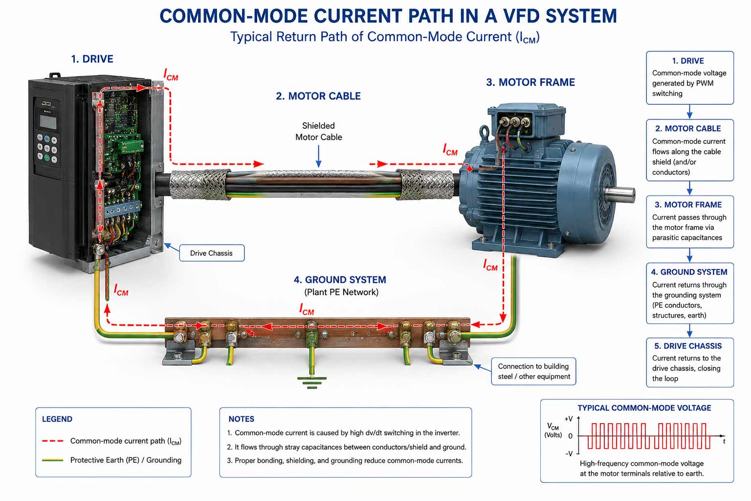
Common-mode currents are often the hidden source of problems that appear unrelated to the drive. Industrial Ethernet networks may suffer packet loss or intermittent disconnects. Analog measurements, encoder signals, and temperature readings may become unstable. PLCs may experience unexpected resets or false triggering.
Radiated Emissions
Radiated emissions occur when electrical energy is converted into electromagnetic fields that propagate through space. Unlike conducted disturbances, radiated emissions do not require direct electrical connections. They can disturb equipment several meters away.
In VFD installations, the drive enclosure itself is not always the main radiator. Motor cables, ground conductors, shield terminations, and structural metallic elements often act as antennas. Long motor cables are especially important because a cable several tens of meters long can radiate efficiently if it is not correctly shielded, bonded, and routed.
Radiated emissions may interfere with wireless communication systems, industrial Wi-Fi, RFID systems, instrumentation equipment, medical devices, and radio communications. In severe cases, intermittent operational problems may affect an entire production line or facility.
Harmonics and Interharmonics
Harmonics are frequency components that occur at integer multiples of the fundamental power frequency. In a 60 Hz system, the 2nd harmonic is 120 Hz, the 3rd is 180 Hz, the 5th is 300 Hz, and the 7th is 420 Hz. Variable frequency drives are among the most common harmonic-generating loads in industrial facilities.
Excessive harmonics may cause transformer overheating, cable heating, capacitor failures, and reduced equipment lifetime. Total Harmonic Distortion (THD) is often used to quantify the severity of harmonic distortion. Higher THD generally means poorer power quality and greater risk of operational problems.
Interharmonics occur at frequencies that are not integer multiples of the fundamental frequency. They may arise from VFDs, cycloconverters, and advanced power electronic systems. Interharmonics can produce flicker, oscillatory phenomena, and resonance problems. Their behavior is often harder to predict than traditional harmonics. For power electronics and drive systems, harmonic and flicker testing helps evaluate these power-quality risks before market entry or installation.
Bearing Currents and Reflected Waves
One of the most expensive consequences of poor EMC design is motor bearing damage. Common-mode voltages generated by PWM switching can induce shaft voltages. When the voltage exceeds the insulation capability of the bearing lubricant film, electrical discharge may occur through the bearing.
This discharge may cause pitting, fluting, unusual bearing noise, increased vibration, elevated temperatures, and premature bearing failure. These failures are often mistakenly attributed to purely mechanical causes.
Long motor cables can create another issue: reflected waves. High-speed voltage transitions travel along the cable and reflect at impedance discontinuities. The resulting voltage overshoots can increase motor insulation stress and reduce equipment lifetime.
EMC Challenges in Modern Industrial Facilities
Modern industrial facilities combine VFDs, robotics, PLCs, industrial Ethernet, wireless systems, cloud-connected devices, sensors, and advanced automation platforms. As these systems become more interconnected, a disturbance generated by one drive may affect many other systems.
The cost of poor EMC is not limited to a failed test report. It may include production downtime, quality issues, maintenance expenses, warranty claims, safety risks, and delayed project deployment.
Real-World EMC Failure Examples
Intermittent PLC Resets
A manufacturing facility experienced random PLC failures. After extensive investigation, the issue was traced to common-mode currents from a nearby drive coupling into communication wiring.
Encoder Malfunctions
A high-speed production line suffered position feedback errors. The root cause was radiated interference from improperly shielded motor cables.
Wireless Network Instability
An industrial Wi-Fi network experienced intermittent outages. The source was eventually traced to conducted and radiated disturbances from multiple VFD installations.
Why Early EMC Design Matters
Correcting EMC issues after installation is often expensive and disruptive. Common corrective actions may include additional filters, cable replacement, grounding modifications, shielding retrofits, equipment relocation, and repeated troubleshooting visits.
These changes usually cost far more than applying proper EMC design principles during the product development and system integration stages. Early EMC review, pre-compliance testing, and clear installation instructions can significantly reduce the risk of field problems.
Practical EMC Design and Installation Practices
- Use EMC filters selected for the drive rating, installation category, and target environment.
- Keep motor cables as short as practical.
- Use shielded motor cables where required by the application and standard.
- Terminate cable shields with 360-degree bonding instead of long pigtails.
- Separate motor cables, power cables, control wiring, and communication cables.
- Use low-impedance grounding and equipotential bonding.
- Consider output reactors, dV/dt filters, or sine filters for long motor cable applications.
- Evaluate harmonics, interharmonics, and power quality during the design phase.
- Document EMC installation requirements clearly for installers and end users.
How Stancer Testing-Lab Can Help
Stancer Testing-Lab, an accredited EMC Test Lab and RF Testing Lab (or wireless testing Lab) supports manufacturers, integrators, and engineering teams with accredited EMC testing and compliance support for industrial electronics, motor drives, automation systems, and power conversion equipment.
Our capabilities include conducted emissions testing, radiated emissions testing, radiated immunity testing, conducted immunity testing, harmonic and flicker testing, RF testing, and EMC pre-compliance testing.
Stancer Testing-Lab in the position of a leading EMC Test Lab and a fully equipped RF Testing Lab is able to perform EMC testing on 3-phase motor drives and power electronics converter up to 200-A.
Whether the objective is IEC 61800-3 compliance, EMC certification, CE marking, product validation, or early design troubleshooting, structured testing helps identify risks before they become expensive field problems.
References
- IEC 61800-3:2017, Adjustable Speed Electrical Power Drive Systems – Part 3: EMC Requirements and Specific Test Methods.
- Keith Armstrong, Complying with IEC/EN 61800-3 – Good EMC Engineering Practices in the Installation of Power Drive Systems.
- EMC Notes for the Application of the Product Standard EN 61800-3.
- IEC 61000-4 Series, Electromagnetic Compatibility (EMC) – Testing and Measurement Techniques.
- IEC 61000-3-2, Limits for Harmonic Current Emissions.
- IEC 61000-4-13, Harmonics and Interharmonics Immunity Tests.
- Ott, H. W., Electromagnetic Compatibility Engineering, Wiley.
- Clayton R. Paul, Introduction to Electromagnetic Compatibility, Wiley.
- Henry W. Ott, Noise Reduction Techniques in Electronic Systems, Wiley.
Need support with EMC testing for VFDs, industrial electronics, or power drive systems? Contact Stancer Testing-Lab to discuss your project requirements and compliance objectives.