Conducted Emission
Conducted Emissions Testing: Why It Matters for EMC Compliance
Conducted emissions are unwanted electrical disturbances that travel along power lines, signal cables, DC inputs, communication ports, or wiring harnesses. Unlike radiated emissions, which propagate through space, conducted emissions move through conductors and can disturb other equipment connected to the same electrical network.
For manufacturers, conducted emissions testing is one of the most important parts of EMC testing. It helps confirm that a product does not inject excessive electrical noise into the mains supply, DC power lines, or connected systems.
What Are Conducted Emissions?
Conducted emissions are high-frequency voltage or current disturbances generated by electronic equipment and transferred through cables. They are commonly produced by switching power supplies, motor drives, LED drivers, battery chargers, inverters, digital processors, clocks, and power converters.
Most conducted emissions testing for AC mains ports is performed from 150 kHz to 30 MHz. This frequency range is important because noise in this band can travel efficiently through power distribution networks and interfere with nearby electronic equipment, communication systems, medical devices, industrial controls, and radio receivers.
Engineering insight: A product can pass functional testing perfectly and still fail conducted emissions. The circuit may regulate, charge, switch, or communicate correctly while injecting too much high-frequency noise back onto the power line.
Why Conducted Emissions Testing Is Important
Conducted emissions testing ensures that electronic products can operate in a shared electromagnetic environment without disturbing other devices. This is essential for regulatory approval, product reliability, and customer confidence.
Regulatory Compliance
Standards such as CISPR, IEC, EN, FCC, and industry-specific EMC standards define conducted emission limits for different product categories and environments.
Product Reliability
Excessive conducted noise can disturb nearby systems, communication lines, sensors, controllers, and power supplies.
Market Access
Products that fail conducted emissions may face certification delays, redesign costs, customs issues, or market restrictions.
Design Confidence
Early testing helps engineers identify noise sources before formal certification, reducing the risk of late-stage failure.
Common-Mode and Differential-Mode Conducted Emissions
Conducted emissions are usually divided into two categories: common-mode noise and differential-mode noise. Understanding the difference is essential because each type requires different mitigation techniques.
| Noise Type | How It Flows | Typical Source | Common Mitigation |
|---|---|---|---|
| Common-Mode Noise | Flows in the same direction on multiple conductors and returns through parasitic capacitance, chassis, or earth. | Switching power supplies, parasitic capacitance, fast dv/dt nodes, motor drives. | Common-mode chokes, Y capacitors, chassis bonding, shielding, improved layout. |
| Differential-Mode Noise | Flows between line and neutral, positive and negative, or supply and return conductors. | Input current ripple, rectifiers, DC-DC converters, pulsed loads. | X capacitors, differential inductors, LC filters, reduced loop area. |
How Conducted Emissions Are Measured
Conducted emissions testing is performed using a controlled setup that provides repeatable measurement conditions. The equipment under test is powered through a measurement network, and the noise appearing on the power line is measured with an EMI receiver or spectrum analyzer.
Key Test Equipment
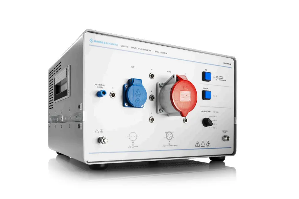
- LISN: A Line Impedance Stabilization Network provides standardized impedance and couples conducted noise to the measurement receiver.
- EMI Receiver: Measures emission levels using standardized bandwidths and detector functions such as peak, quasi-peak, and average.
- Spectrum Analyzer: Often used for pre-compliance scans and troubleshooting.
- Shielded Environment: Helps reduce the influence of external noise and improves measurement confidence.
What Is a LISN?
A Line Impedance Stabilization Network, or LISN, is one of the most important instruments in conducted emissions testing. It performs two main functions. First, it presents a standardized impedance to the device under test. Second, it isolates the test from external power-line noise while allowing the emissions generated by the product to be measured accurately.
Without a LISN, the measured noise could change depending on the building wiring, power source impedance, cable routing, or ambient electrical noise. That would make results difficult to reproduce and unsuitable for formal compliance decisions.
Laboratory observation: Many conducted emission failures are not caused by a missing filter, but by a filter placed too far from the connector. If noise reaches the cable before the filter, the product may fail even though the schematic appears correct.
Why Conducted Emission Limit Lines Are Different
Conducted emission limits depend on the product type, operating environment, power connection, and applicable standard. A residential product usually faces stricter limits than equipment intended for industrial environments because it may operate close to radios, consumer electronics, home networks, and sensitive household equipment.
| Category | Typical Environment | Compliance Consideration |
|---|---|---|
| Class A Equipment | Industrial or commercial environments | Generally allowed higher emissions than residential products. |
| Class B Equipment | Residential, commercial, and light industrial environments | Usually subject to stricter limits because nearby devices may be more sensitive. |
| Medical Devices | Hospitals, clinics, home healthcare | Often evaluated under IEC 60601-1-2 with attention to safety and essential performance. |
| Automotive Electronics | Vehicles and electrical/electronic sub-assemblies | May require CISPR 25, ISO 7637, ISO 16750-2, or OEM-specific requirements. |
Standards Commonly Used for Conducted Emissions
The applicable conducted emissions standard depends on the product category and target market. Common examples include:
- CISPR 11: Industrial, scientific, and medical equipment.
- CISPR 14: Household appliances and tools.
- CISPR 15: Lighting equipment.
- CISPR 25: Automotive components and on-board receiver protection.
- CISPR 32: Multimedia and information technology equipment.
- IEC 60601-1-2: Medical electrical equipment EMC.
- IEC 61326: Measurement, control, and laboratory equipment.
- FCC Part 15: Radiofrequency devices marketed in the United States.
For products with intentional transmitters, conducted emissions may also need to be considered alongside RF testing, wireless certification, spurious emissions, and radio regulatory requirements.
Common Causes of Conducted Emissions Failures
Most conducted emission failures come from predictable design issues. The earlier these are identified, the easier they are to correct.
| Failure Source | Why It Creates Noise | Practical Fix |
|---|---|---|
| Switching power supply | Fast current transitions create harmonics and input ripple. | Reduce hot-loop area, improve input filtering, optimize layout. |
| Motor drive or inverter | PWM switching creates high dv/dt and common-mode current. | Use common-mode chokes, shielding, snubbers, and proper grounding. |
| LED driver | Switching current and PWM dimming create spectral components. | Improve filtering and route LED current loops carefully. |
| USB charger or battery charger | Power conversion and charging transitions generate line noise. | Test all charging modes and add input/output filtering. |
| Poor PCB layout | Large current loops and uncontrolled return paths increase noise coupling. | Use short loops, continuous reference planes, and connector-level filtering. |
EMI Filter Design for Conducted Emissions
EMI filters reduce conducted noise before it reaches the external cable or power line. A good filter is not only a set of components. It is a physical structure whose performance depends heavily on placement, grounding, parasitic coupling, and source/load impedance.
Common Filter Components
- X capacitors: Used across line and neutral or supply conductors to reduce differential-mode noise.
- Y capacitors: Used from line or DC rails to chassis/earth to control common-mode noise.
- Common-mode chokes: Attenuate noise flowing in the same direction on multiple conductors.
- Differential inductors: Reduce noise flowing between supply conductors.
- Ferrite beads: Provide frequency-dependent impedance for high-frequency noise suppression.
- Damping networks: Reduce filter resonance and prevent peaking.
Design tip: Place the conducted emissions filter as close as possible to the cable or power entry point. Noise should be filtered before it reaches the external conductor, not after it has already coupled onto the cable.
Conducted Emissions vs. Radiated Emissions
Conducted and radiated emissions are closely connected. Noise that begins as conducted current on a cable can become radiated emissions if that cable acts like an antenna. Similarly, a radiating PCB trace can couple noise into a harness or power lead.
This is why a complete EMC program often includes both conducted emission testing and radiated emission testing. Evaluating only one mechanism can miss the real coupling path.
When Should Conducted Emissions Testing Begin?
Conducted emissions should be evaluated early, ideally during prototype development. Waiting until final certification increases the risk of redesign, PCB re-spin, enclosure changes, and market delays.
Early EMC pre-compliance testing can quickly identify dominant frequencies, noise modes, filter weaknesses, and operating conditions that create the highest emissions.
How Stancer Testing-Lab Can Help
Stancer Testing-Lab supports manufacturers with conducted emissions testing, full EMC testing, RF testing, radiated emissions, immunity testing, troubleshooting, and regulatory planning for North American and international markets.
Our team helps manufacturers identify conducted noise sources, evaluate filter performance, understand applicable standards, and prepare products for formal certification.
Frequently Asked Questions
What is conducted emissions testing?
Conducted emissions testing measures unwanted electrical noise that travels along power lines, DC inputs, signal cables, or communication ports from a device under test.
What frequency range is used for conducted emissions?
For many AC mains tests, conducted emissions are measured from 150 kHz to 30 MHz. Other ranges may apply depending on the product and standard.
What is a LISN used for?
A LISN provides standardized impedance, isolates power-line noise, and couples emissions from the device under test to the EMI receiver.
What is the difference between common-mode and differential-mode noise?
Differential-mode noise flows between conductors. Common-mode noise flows in the same direction on multiple conductors and returns through parasitic or chassis paths.
Why do switching power supplies fail conducted emissions?
Switching power supplies create fast current transitions and harmonic content. Poor layout, large hot loops, and weak input filtering often make conducted emissions worse.
Can conducted emissions cause radiated emissions?
Yes. Noise conducted onto cables can radiate if the cable behaves like an antenna, especially when common-mode current is present.
What is the difference between Class A and Class B conducted emission limits?
Class A limits generally apply to industrial or commercial equipment. Class B limits are stricter and typically apply to residential or consumer products.
Can pre-compliance testing identify conducted emissions problems?
Yes. Pre-compliance testing can identify dominant noise frequencies, operating modes, and filter weaknesses before formal certification.
What causes conducted emissions on DC power lines?
DC conducted emissions can come from DC-DC converters, battery chargers, motor drives, digital switching circuits, and power path controllers.
How can manufacturers reduce conducted emissions?
Common methods include better PCB layout, reduced current-loop area, EMI filtering, common-mode chokes, proper grounding, shielding, and early pre-compliance testing.
Conclusion
Conducted emissions are a critical part of EMC compliance. They reveal how much unwanted electrical noise a product sends back through its power or signal connections. If not controlled, this noise can disturb nearby equipment, degrade communication systems, and prevent regulatory approval.
By understanding common-mode and differential-mode noise, using proper LISN-based measurement methods, designing filters carefully, and testing early, manufacturers can significantly reduce the risk of certification failure.
Stancer Testing-Lab provides professional conducted emissions testing and EMC compliance support to help manufacturers bring reliable, compliant products to market with confidence.