
Automotive EMC Emission and Compliance Testing
Automotive EMC Emissions Testing: Standards, Methods, Chamber Requirements, and Best Practices
Electromagnetic emissions are now a central part of vehicle compliance, product reliability, and functional safety. Modern vehicles contain power converters, electric propulsion systems, battery management electronics, ECUs, radar sensors, telematics, infotainment networks, cellular modules, V2X communication, and high-speed data buses. Each of these systems can become either a source of electromagnetic interference or a victim of it. For that reason, EMC testing is no longer a late-stage paperwork exercise; it is a design and validation discipline that directly affects vehicle performance, OEM acceptance, and market access.
Automotive emissions testing focuses on unwanted electromagnetic energy produced by vehicles, electronic sub-assemblies, cables, modules, motors, inverters, chargers, and control electronics. Some emissions travel through harnesses and power leads as conducted noise. Others radiate from wiring, PCB structures, enclosures, or the complete vehicle body. In both cases, the objective is the same: confirm that the vehicle or component does not interfere with on-board receivers, off-board receivers, nearby equipment, infrastructure, or safety-related systems.
The automotive sector is different from many other industries because compliance is driven by both formal regulations and OEM-specific engineering requirements. A supplier may need to satisfy international standards such as CISPR 12, CISPR 25, CISPR 36, ISO 11452, ISO 7637, ISO 10605, and UNECE Regulation No. 10, while also meeting internal specifications from an OEM. A well-structured automotive EMC testing program helps bring these requirements into one defensible compliance path.
Why Automotive Electromagnetic Emissions Matter
A vehicle is a dense electromagnetic environment. Low-voltage electronics, high-voltage traction systems, communication buses, sensors, motors, switching regulators, wireless transmitters, and charging interfaces operate in close proximity. If emissions are not controlled, they can create intermittent failures that are difficult to reproduce during normal troubleshooting.
In practical terms, excessive automotive emissions can:
- Interfere with safety-critical systems such as ABS, ESC, airbag controllers, power steering, and ADAS sensors.
- Reduce the performance of on-board receivers, including AM/FM radio, GPS, cellular, Bluetooth, Wi-Fi, keyless entry, and V2X systems.
- Disturb nearby off-board receivers such as broadcast radio, residential equipment, public infrastructure, and communication services.
- Introduce noise into sensor wiring, diagnostic lines, CAN, LIN, Automotive Ethernet, and high-speed data links.
- Create integration problems when an otherwise acceptable module is installed inside a complete vehicle architecture.
- Delay OEM approval, type approval, or product launch when failures appear late in the validation program.
In automotive EMC, passing a component test is only part of the story. The real objective is controlled electromagnetic behavior after the component is installed in the vehicle, connected to the final harness, powered by the vehicle electrical system, and operated in realistic modes.
The Regulatory and Standards Landscape
Automotive EMC standards are developed and maintained primarily by CISPR, ISO, and SAE. CISPR standards mainly address radio disturbance and emissions measurement. ISO standards cover many immunity and electrical disturbance methods for vehicles and components. SAE standards remain important in North America, although many SAE documents have been withdrawn as complete standards and retained mainly to document differences from equivalent CISPR or ISO standards.
In addition to these international standards, vehicle manufacturers maintain internal corporate specifications. These OEM specifications often reference CISPR and ISO documents but may impose different severity levels, operating modes, harness configurations, reporting expectations, or pass/fail criteria. For suppliers, the test plan must reflect both the applicable standard and the OEM program requirement.
| Standard or Regulation | Main Purpose | Typical Application |
|---|---|---|
| CISPR 25 | Radio disturbance characteristics for protecting receivers used on board vehicles, boats, and devices. | Component-level conducted and radiated emissions; vehicle antenna-port noise evaluation. |
| CISPR 12 | Radio disturbance limits and methods for protecting off-board receivers. | Complete vehicles, boats, and internal combustion engine devices; vehicle radiated emissions. |
| CISPR 36 | Radio disturbance characteristics below 30 MHz for electric and hybrid electric road vehicles. | Low-frequency emissions from electric propulsion vehicles, typically measured using loop antennas. |
| ISO 11452-2 | Component immunity to radiated electromagnetic fields in an absorber-lined shielded enclosure. | Radiated immunity testing, typically from 200 MHz to 18 GHz. |
| ISO 7637 series | Electrical transient conduction and coupling. | Transient immunity and emissions on supply lines and I/O lines. |
| ISO 10605 | Electrostatic discharge test methods for road vehicles. | ESD testing at component or vehicle level. |
| UNECE Regulation No. 10 | Regulatory EMC requirements for wheeled vehicles and electronic sub-assemblies. | Vehicle type approval and ESA approval, especially for markets using UNECE regulations. |
| FCC Part 15 | U.S. radio-frequency emission requirements for electronic devices. | Unintentional radiator evaluation and RF emission control for products sold in the United States. |
CISPR 12, CISPR 25, and CISPR 36: Knowing Which Standard Applies
CISPR 12 and CISPR 25 are often mentioned together, but they do not serve the same purpose. CISPR 12 is concerned with protecting off-board receivers. In plain language, it addresses whether a vehicle or engine-powered device could interfere with radio or communication equipment outside the vehicle. CISPR 25 focuses on receivers installed on board the vehicle. It asks whether the vehicle’s own electronics will degrade the performance of its own antennas and communication systems.
CISPR 36 adds another important layer for electric and hybrid electric road vehicles. It addresses radio disturbance characteristics below 30 MHz for the protection of off-board receivers. This is increasingly relevant because electrified powertrains, traction inverters, high-current switching, and charging systems can produce low-frequency magnetic-field and conducted/radiated phenomena that are not always well represented by older internal-combustion vehicle assumptions.
| Use Case | Relevant Standard | Engineering Interpretation |
|---|---|---|
| Complete vehicle emissions affecting nearby radio or communication systems | CISPR 12 | Protects off-board receivers and is often linked to regulatory requirements. |
| Vehicle electronics affecting the vehicle’s own radio, GPS, telematics, or communication receivers | CISPR 25 | Protects on-board receivers and is widely used in OEM supplier qualification. |
| Electric or hybrid vehicle low-frequency emissions below 30 MHz | CISPR 36 | Addresses specific emission concerns associated with electric propulsion systems. |
| Vehicle or ESA regulatory approval | UNECE R10 | Provides a regulatory framework and references CISPR methods for setups and measurement techniques. |
Vehicle-Level Versus Component-Level Testing
Automotive EMC programs usually include both vehicle-level and component-level evaluations. Vehicle-level testing evaluates the integrated system, including body structure, harness routing, grounding, antennas, power distribution, and realistic operating modes. Component-level testing focuses on an electronic module or electrical/electronic sub-assembly before final integration.
Component testing is especially important because it allows suppliers to identify emissions problems before the module reaches the OEM integration stage. A module that performs poorly on the bench may become far more difficult to correct once it is installed inside a vehicle, connected to a long harness, and operated near sensitive receivers.
Vehicle-Level Testing
Assesses the complete vehicle, including antennas, harnesses, grounding paths, propulsion systems, charging modes, and integrated electronics.
Component-Level Testing
Evaluates ECUs, modules, inverters, converters, sensors, chargers, and ESAs before vehicle integration.
Engineering Validation
Supports early troubleshooting and design improvement before formal design verification or product validation testing.
Radiated Emissions Testing in Automotive Applications
Radiated emissions testing measures electromagnetic fields that leave the vehicle or component through space. In automotive systems, the strongest radiator is not always the electronic module itself. More often, harnesses, long cables, motor leads, enclosure seams, ground returns, display cables, and high-voltage conductors become the dominant radiation structures.
For CISPR 12 vehicle measurements, radiated emissions are typically measured at 3 m or 10 m distances, with limits intended to protect receivers at a distance of 10 m or more. Measurements may be performed on an open test site or in an absorber-lined shielded enclosure when the chamber can be correlated to an outdoor test site. For boats, measurements may also be performed on water when appropriate.
For CISPR 25 component measurements, radiated emissions are performed in a controlled chamber environment. The setup is very sensitive to bench geometry, cable routing, antenna distance, ground plane bonding, and ambient noise. This is why a component that passes in one poorly controlled configuration may fail when tested using a properly defined harness layout or operating mode.
Conducted Emissions and Harness Noise
Conducted emissions testing measures unwanted noise currents and voltages travelling along power leads, signal lines, and harnesses. In automotive applications, conducted noise is often the first clue that a switching regulator, motor driver, inverter, DC-DC converter, battery charger, or communication interface is coupling energy into the vehicle electrical system.
Line Impedance Stabilization Networks, current probes, voltage probes, artificial networks, and defined harness configurations are used to create repeatable measurement conditions. The reason is simple: harness impedance and routing change the result. Without a defined setup, the measurement may describe the test arrangement more than the product.
The Test Bench Is Part of the Measurement System
One of the most important practical lessons from CISPR 25 is that the cable harness is not a minor accessory. At lower frequencies, where the electronic module may be electrically small, the harness can become the main structure that couples energy to the measurement antenna. The bench, ground plane, LISN, harness position, cable length, and grounding method all influence the result.
For component radiated emissions under CISPR 25, the reference ground plane must be large enough to support the EUT and the required harness. A common benchmark is a minimum width of 1000 mm and a minimum length of 2000 mm, or the length needed to support the EUT plus 200 mm, whichever is greater. The ground plane is often bonded to the shielded enclosure wall, which can help reduce resonant effects in the 10 MHz to 70 MHz region when hybrid absorber is used.
In automotive component emissions testing, the harness is often the antenna. A clean PCB layout helps, but poor cable routing, weak bonding, missing filtering, or uncontrolled return paths can dominate the final emissions profile.
ALSE Chamber Requirements and Ambient Noise
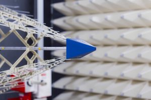
An absorber-lined shielded enclosure, or ALSE, combines shielding and RF absorber to create a controlled test environment. The shielded room blocks external RF signals so the equipment under test remains the dominant source of measured emissions. The absorber reduces internal reflections so the coupling path between the EUT and antenna is more predictable.
CISPR 25 requires the electromagnetic noise level in the test area to be sufficiently below the measured limit. In practice, the ambient level is expected to be at least 6 dB lower than the lowest level being measured. Since some CISPR 25 radiated emissions limits are very low, chamber shielding, receiver performance, cable hygiene, grounding, and ambient validation become critical.
The current CISPR 25 frequency range extends from 150 kHz to 5.95 GHz for relevant measurements. At low frequencies, absorber materials cannot provide the same kind of absorption seen at higher frequencies, but the chamber is electrically small enough that strong resonant behavior is less of a concern. At higher frequencies, absorber performance becomes much more important because chamber resonances can create significant measurement error.
Antenna Selection in CISPR 25 Measurements
Antenna choice is not just a convenience issue. CISPR 25 references antenna types aligned with CISPR 16 guidance. Typical selections include an active rod monopole at low frequencies, a biconical antenna from 30 MHz to 200 MHz, a log-periodic dipole array from 200 MHz to 1 GHz, and a dual-ridge horn from 1 GHz to 5.95 GHz. Bi-log antennas are not permitted for CISPR 25 measurements in the current edition because the standard has removed references to them.
| Frequency Range | Typical Antenna | Practical Note |
|---|---|---|
| Low-frequency range | Active rod monopole | Used where electric-field measurements require a small active antenna structure. |
| 30 MHz to 200 MHz | Biconical antenna | Common choice for lower VHF emissions measurements. |
| 200 MHz to 1 GHz | Log-periodic dipole array | Often drives chamber length due to antenna size and required clearance. |
| 1 GHz to 5.95 GHz | Dual-ridge horn antenna | Compact and efficient for higher-frequency automotive emissions measurements. |
Electric and Hybrid Vehicles Add New EMC Conditions
Electric and hybrid vehicles create additional EMC challenges because of high voltage, high current, fast switching, battery charging, regenerative braking, traction inverters, and large cable structures. The vehicle is no longer only a transportation platform; during charging, it also becomes a grid-connected electrical system. That changes the relevant operating modes and the possible emission paths.
CISPR 25 includes special setups for EVs, HEVs, and modules used in those vehicles, such as batteries, inverters, converters, and related electronics. UNECE R10 also requires attention to vehicle conditions when connected to mains or charging infrastructure. For this reason, an automotive EMC test plan should clearly define propulsion state, charging state, battery state of charge, cable configuration, load condition, and communication activity with the charger.
For Stancer projects involving electric vehicles, motor drives, power converters, or high-current power electronics, emissions testing is most effective when combined with early EMC pre-compliance testing. This allows engineers to identify problems before final harnesses, shielding, filters, and mechanical packaging become difficult to modify.
Radiated Immunity and ISO 11452-2
Although this article focuses on emissions, automotive EMC cannot be separated from immunity. A vehicle component must not only avoid disturbing others; it must also continue to operate when exposed to electromagnetic fields. Radiated immunity testing under ISO 11452-2 evaluates component behavior in an absorber-lined shielded enclosure over a frequency range commonly extending from 200 MHz to 18 GHz.
ISO 11452-2 uses severity levels such as 25 V/m, 50 V/m, 75 V/m, and 100 V/m, with higher levels possible depending on the user of the standard or OEM requirement. Below 200 MHz, antenna-based field generation becomes less efficient and physically larger, so other ISO 11452 methods such as bulk current injection, TEM cell, and stripline testing are often more practical.
| ISO 11452-2 Severity Level | Typical Field Strength | Interpretation |
|---|---|---|
| Level I | 25 V/m | Lower severity immunity evaluation. |
| Level II | 50 V/m | Moderate RF immunity requirement. |
| Level III | 75 V/m | Higher automotive immunity expectation. |
| Level IV | 100 V/m | Common high-level automotive immunity target. |
| Level V | User-defined | Used where OEM or application-specific requirements exceed standard levels. |
Other Automotive EMC Test Categories
A complete automotive EMC program goes well beyond radiated emissions. The main test areas usually include radiated RF emissions, conducted RF emissions, radiated RF immunity, conducted transient immunity, conducted transient emissions, and electrostatic discharge. Each test examines a different coupling mechanism and therefore a different design risk.
| Test Area | Typical Standards | What It Reveals |
|---|---|---|
| Radiated RF Emissions | CISPR 12, CISPR 25, CISPR 36 | Unwanted fields radiated from vehicles, components, cables, and propulsion systems. |
| Conducted RF Emissions | CISPR 25 | Noise carried on power and signal conductors. |
| Radiated RF Immunity | ISO 11452-2, ISO 11451 series | Component or vehicle response to external RF fields. |
| Conducted Immunity | ISO 11452-4, ISO 11452-7, ISO 7637 | Robustness against injected RF or transient disturbances on cables. |
| Conducted Transient Emissions and Immunity | ISO 7637 series, ISO 16750-2 | Electrical disturbances caused by switching, load changes, reverse voltage, or ground offset. |
| Electrostatic Discharge | ISO 10605 | Vehicle or component behavior under ESD events from human interaction or handling. |
Creating an Automotive EMC Test Plan
A strong automotive EMC test plan must be prepared before formal design verification or product validation begins. It should define the product, variants, operating modes, sample quantity, support equipment, monitoring methods, acceptance criteria, and OEM-specific requirements. It should also identify whether the activity is engineering validation, design verification, or product validation.
At minimum, the test plan should address:
- The product, module, system, or vehicle configuration to be tested.
- All product options, software variants, hardware variants, and representative worst-case configurations.
- Inputs and outputs required to trigger each normal mode of operation.
- Modes that help isolate broadband noise, narrowband noise, or specific functional blocks.
- Baseline performance monitoring, including tolerances and functional response criteria.
- Pin-out diagrams, harness drawings, load simulators, support equipment, and software tools.
- Orthogonal orientations of the device, documented with diagrams or photographs.
- Power and ground lines requiring transient testing.
- Pass/fail criteria, severity levels, environmental conditions, safety procedures, and reporting expectations.
- OEM communication procedures when a test condition must be modified during the program.
A test plan is not only a laboratory instruction sheet. It is a contract between design intent, OEM expectations, standards requirements, and the evidence that will later support compliance.
Working With a Third-Party Automotive EMC Laboratory
When suppliers work with a third-party EMC laboratory, several details should be clarified before the test campaign begins. Who provides the loads, fixtures, actuators, control software, cables, power supplies, and communication tools? How will the component response be monitored inside the chamber? What happens if a test condition cannot be executed exactly as written? Who communicates with the OEM if a deviation is needed?
These questions matter because automotive EMC testing is often performed under tight program deadlines. In many OEM programs, the supplier may need to provide rapid pass/fail updates, followed by detailed test reports within a short window. Close communication between the supplier, OEM, and laboratory helps prevent minor setup issues from becoming schedule delays.
As an ISO/IEC 17025 accredited testing laboratory, Stancer Testing-Lab supports manufacturers with structured test planning, formal EMC measurements, pre-compliance troubleshooting, and practical guidance for vehicle and ESA programs.
Design Controls That Improve Emissions Performance
Automotive emissions performance is strongly influenced by early engineering decisions. Once the PCB, enclosure, connector system, harness, and mechanical packaging are frozen, corrective actions become harder and more expensive. The most effective emissions strategy is therefore preventive rather than reactive.
Design teams should focus on:
- Stable return paths for high-speed and switching currents.
- Controlled cable routing and separation between noisy and sensitive circuits.
- Proper shield termination and 360-degree bonding where appropriate.
- Input and output filtering matched to the actual noise source and impedance environment.
- Minimizing loop area in power electronics and motor drive circuits.
- Reducing common-mode current on harnesses and long cables.
- Managing DC-DC converter switching frequency, edge rate, layout, and grounding.
- Validating worst-case operating modes, not only nominal steady-state operation.
- Coordinating EMC fixes with thermal, mechanical, functional safety, and RF performance requirements.
OEM Expectations and Supplier Responsibility
Many OEMs require compliance with internal standards that are stricter or more detailed than baseline international standards. Specifications such as GMW, Ford, Stellantis/FCA, Jaguar Land Rover, and other manufacturer-specific documents may define unique test levels, setup details, monitoring rules, functional classifications, and reporting requirements. The supplier is usually responsible for proving that the component meets these requirements before it is accepted for integration.
This is why suppliers should not treat CISPR 25 or ISO 11452-2 as the entire requirement set. They are often the foundation, but the OEM specification determines the final acceptance criteria. For broader regulatory planning, manufacturers may also need to consider FCC compliance, ISED requirements, CE marking, and global market access.
How Stancer Testing-Lab Supports Automotive Emissions Programs
Stancer Testing-Lab supports automotive manufacturers, suppliers, and engineering teams with EMC and RF testing services for vehicles, ESAs, industrial electronics, power electronics, and connected products. Our automotive EMC support can include radiated emissions, conducted emissions, radiated immunity, conducted immunity, ESD testing, pre-compliance investigation, and compliance planning.
For vehicle-level and component-level programs, early engagement helps define the correct standards, operating modes, test setup, sample requirements, harness configuration, and documentation path. This reduces the risk of failed tests, repeated chamber time, delayed OEM submissions, and late-stage redesign.
Frequently Asked Questions
Automotive EMC Emissions Testing FAQs
What is automotive EMC emissions testing?
Automotive EMC emissions testing measures unwanted electromagnetic energy generated by vehicles, ECUs, electronic modules, motors, inverters, harnesses, and power electronics. The goal is to confirm that emissions remain below defined limits and do not interfere with on-board receivers, nearby vehicles, infrastructure, or communication systems.
What is the difference between CISPR 12 and CISPR 25?
CISPR 12 focuses on emissions that may affect off-board receivers outside the vehicle, while CISPR 25 focuses on protecting receivers installed on board the vehicle. CISPR 25 is especially important for telematics, GPS, radio, keyless systems, and connected vehicle electronics.
When does CISPR 36 apply?
CISPR 36 applies to electric and hybrid electric road vehicles and addresses radio disturbance characteristics below 30 MHz for the protection of off-board receivers. It is relevant for low-frequency phenomena associated with electric propulsion systems.
Why is the cable harness so important in CISPR 25 testing?
At many automotive EMC frequencies, especially lower frequencies, the cable harness can become the dominant radiator. Harness length, routing, grounding, shielding, and load configuration can strongly affect radiated and conducted emissions results.
What is an ALSE chamber?
An absorber-lined shielded enclosure is a shielded room lined with RF absorber. It blocks outside radio noise and reduces internal reflections, creating a repeatable environment for automotive EMC emissions and immunity testing.
What ambient noise level is required for CISPR 25 testing?
CISPR 25 requires the electromagnetic noise level in the test area to be sufficiently below the measurement limit. A common requirement is that ambient noise be at least 6 dB lower than the lowest level being measured.
Why do EVs and hybrid vehicles create additional EMC challenges?
EVs and HEVs contain high-voltage systems, high-current switching, traction inverters, battery systems, charging interfaces, and long power cables. These systems can generate emissions during driving, charging, regenerative braking, and stationary operating modes.
What is ISO 11452-2 used for?
ISO 11452-2 is used for component-level radiated immunity testing in an absorber-lined shielded enclosure, commonly from 200 MHz to 18 GHz. It evaluates whether a component continues to function when exposed to RF fields.
Should automotive EMC testing start before the final design is complete?
Yes. Early pre-compliance testing is strongly recommended because emissions problems are much easier to correct before PCB layout, harness design, enclosure geometry, shielding, filtering, and mechanical packaging are finalized.
How can Stancer Testing-Lab help with automotive EMC compliance?
Stancer Testing-Lab supports automotive manufacturers and suppliers with EMC pre-compliance, radiated and conducted emissions testing, radiated and conducted immunity testing, ESD testing, test planning, troubleshooting, and compliance documentation for North American and international markets.
Conclusion
Automotive EMC emissions testing is a rigorous engineering discipline that connects standards, chamber performance, harness behavior, vehicle integration, OEM expectations, and market access. CISPR 12, CISPR 25, CISPR 36, ISO 11452-2, ISO 7637, ISO 10605, and UNECE R10 each address a different part of the automotive electromagnetic environment. Understanding how these standards interact is essential for designing reliable vehicles and gaining supplier or regulatory approval.
As vehicles become more electrified, connected, and software-defined, emissions control will only become more important. The best results come from early EMC planning, realistic test modes, controlled harness setups, well-prepared test plans, and collaboration with an experienced accredited laboratory. For manufacturers and suppliers, automotive EMC is not simply a compliance checkpoint; it is a practical tool for building safer, more reliable, and more market-ready vehicle technologies.