FCC Certification and Equipment Authorization for LED Lighting Products
FCC Compliance and Equipment Authorization for LED Lighting Products
Modern LED lighting has transformed residential, commercial, industrial, architectural, and outdoor environments. LED systems are efficient, compact, digitally controllable, and increasingly connected. Behind that performance, however, is a high-frequency electronic driver that can generate radio-frequency noise if it is not designed, installed, and tested properly.
This is why LED lighting products are not treated as simple lamps from a regulatory standpoint. Under FCC rules, many LED lighting devices are considered unintentional radiators because their electronic drivers generate RF energy during normal operation. This guide explains FCC compliance, EMC testing, equipment authorization, and manufacturer obligations for RF LED lighting products, with emphasis on FCC KDB Publication 640677 D01 RF LED Lighting v02 and the practical requirements of FCC Part 15.
What Are RF LED Lighting Devices?
High-Frequency LED Drivers and RF Emissions
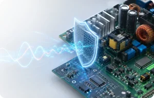
RF LED lighting devices use electronic drivers, most often switch-mode power supplies, to regulate current through LED arrays. These drivers switch rapidly, commonly from tens of kilohertz into the megahertz range. That switching action is efficient and necessary for dimming, current regulation, power factor correction, and thermal management, but it also creates high-frequency electrical noise.
The noise can leave the product in two main ways. It can travel along AC mains wiring, DC wiring, dimming control lines, or communication cables as conducted emissions. It can also radiate from internal wiring, LED boards, metal housings, long strips, cables, driver leads, or enclosure openings as radiated emissions.
Engineering insight: Most LED compliance failures are not caused by the LED chips themselves. They usually originate from the driver topology, PCB layout, input filter design, dimming circuit, cable length, grounding method, or the mechanical integration of the fixture.
Why EMC Matters for LED Products
Although illumination is the primary function of an LED product, the product still shares the electromagnetic environment with radios, Wi-Fi routers, broadcast receivers, medical devices, security systems, industrial controls, smart meters, and communication equipment. Excessive RF noise from a lighting product can degrade radio reception, interfere with nearby electronics, or create customer complaints after installation.
Under FCC Part 15 Subpart B, RF LED lighting products are generally treated as unintentional radiators. That means they must meet emission limits before being marketed in the United States. For Canada, similar planning may be required under ISED requirements. For European market access, LED products may need CE-related EMC testing and, where wireless control is included, RF testing under the Radio Equipment Directive.
Common Examples of RF LED Lighting Products
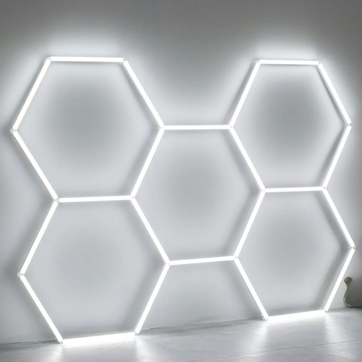
- LED luminaires and ceiling fixtures
- Dimmable LED bulbs and retrofit lamps
- LED strip lights, rope lights, and cabinet lighting
- LED signage, entertainment lighting, stage lighting, and displays
- LED streetlamps and pole-mounted luminaires
- Smart lighting systems with wireless or wired control interfaces
- Industrial high-bay lights and commercial fixtures
- Architectural lighting systems with external drivers or controllers
Why LED Lighting Products Fall Under FCC Rules
Unintentional Radiators Under Part 15
FCC Part 15 applies to radio-frequency devices that can generate RF energy, whether intentionally or unintentionally. LED lighting products with electronic drivers generate switching waveforms that can produce harmonics and broadband noise above 9 kHz. For that reason, they are subject to FCC Part 15 Subpart B emission requirements.
The key point for manufacturers is that a lighting product does not need Wi-Fi, Bluetooth, Zigbee, or another transmitter to fall under FCC rules. A non-wireless LED driver can still be an RF device if it generates RF energy during operation.
Applicable FCC Rules and Test Procedures
| FCC Rule or Procedure | What It Covers | Why It Matters for LED Lighting |
|---|---|---|
| 47 CFR Part 15 Subpart B | Unintentional radiator requirements. | Applies to LED drivers and lighting products that generate RF energy during operation. |
| Section 15.107 | Conducted emission limits on AC power lines. | Controls RF noise returning to the mains supply through power conductors. |
| Section 15.109 | Radiated emission limits, typically from 30 MHz to 1000 MHz for many LED products. | Controls RF energy radiated from the fixture, driver, wiring, housing, or LED assembly. |
| Section 15.5 | General operating conditions. | Devices must not cause harmful interference and must accept interference received. |
| Section 2.906 | Supplier’s Declaration of Conformity. | Defines the SDoC authorization route used by many LED lighting products. |
| Section 2.909 | Responsible party obligations. | Identifies who is responsible for compliance and documentation in the U.S. market. |
FCC KDB 640677 provides specific guidance for RF LED lighting devices, including how to evaluate LED drivers and lighting products across operating conditions that may produce different emission profiles. It is particularly important for products that support multiple output voltages, current levels, dimming modes, driver configurations, or external lamp combinations.
The Four-Corner Test Method for LED Drivers
Worst-Case EMC Evaluation
One of the most important concepts in FCC KDB 640677 is the four-corner testing approach. LED drivers do not always generate their highest emissions at maximum brightness or maximum power. In many cases, worst-case emissions occur at light load, low dimming level, burst-mode operation, or a particular voltage-current combination.
The four-corner method helps demonstrate that the LED driver remains compliant across its rated operating range, rather than only under one convenient test condition.
| Operating Corner | Typical Stress Condition | Why It Can Be EMC-Critical |
|---|---|---|
| Maximum voltage / minimum current | Light-load or high-output-voltage condition. | May trigger burst mode, discontinuous operation, or high-voltage switching noise. |
| Maximum current / minimum voltage | Heavy-load low-voltage condition. | Can increase magnetic field emissions, input ripple, and conducted noise. |
| Maximum voltage and maximum current | Full-power stress condition. | Often produces high thermal and electrical stress, strong switching harmonics, and high input current. |
| Minimum voltage and minimum current | Standby, low dimming, or minimum output condition. | Can reveal control-loop instability, pulse skipping, or dimming-related emissions. |
Laboratory observation: LED drivers often fail at operating points that engineers do not initially expect. A fixture may be quiet at full output but noisy at minimum dimming because the control loop enters pulse-skipping or burst-mode operation.
Testing Integrated and Dimmable Fixtures
Real-World Operating Conditions
Integrated LED fixtures must be tested in representative operating configurations. The driver, LED board, wiring, housing, heat sink, dimming circuit, and mechanical structure all influence the final emission profile. Testing only the driver outside the fixture may not represent the installed product.
Dimmable products require particular care. Emissions should be evaluated at full brightness, minimum output, and intermediate dimming levels likely to produce worst-case operation. Phase-cut dimmers, 0–10 V dimming, DALI control, PWM dimming, and smart lighting controls can each change switching behavior.
Why Dimming Changes EMC Behavior
Dimming modifies the current waveform, duty cycle, control-loop behavior, and sometimes the switching frequency. Some drivers maintain continuous operation across the range; others enter discontinuous, burst, or skip-cycle modes at low output. These modes can create narrowband peaks, broadband noise, or unexpected conducted emissions on AC power lines.
Radiated Emission Frequency Range
Measurements up to 1000 MHz
For many RF LED lighting products, radiated emissions are measured from 30 MHz to 1000 MHz under FCC Part 15 Subpart B. This range is important because switching harmonics, digital control noise, oscillator harmonics, and cable radiation can appear far above the fundamental switching frequency.
Higher-frequency evaluation may be required if the product contains digital circuitry, clocks, wireless control modules, intentional transmitters, or other high-frequency electronics. When a lighting product includes Wi-Fi, Bluetooth, Zigbee, Thread, cellular, or another radio, the test program must also address intentional radiator requirements in addition to unintentional radiator emissions.
Conducted Emission Measurements
AC Mains Noise Control
Section 15.107 covers conducted emissions on AC mains. This is critical for LED lighting because driver noise can return to the power network and propagate through building wiring. In residential and commercial installations, that wiring may be shared with radios, audio equipment, networking devices, medical devices, or other sensitive electronics.
Conducted emissions are typically controlled using AC input filters, common-mode chokes, differential-mode inductors, X capacitors, Y capacitors, ferrites, proper grounding, and careful PCB layout. Filter placement is just as important as component selection; the filter must be located where noise leaves the product.
Design tip: A filter installed several centimeters away from the AC input may not perform as expected. Noise can couple onto the input wiring before the filter can attenuate it.
General Conditions of Operation
FCC Interference Obligations
Under Part 15.5, LED products must not cause harmful interference and must accept interference received. This obligation remains important after the product is shipped. If a lighting product causes harmful interference in the field, the responsible party may need to take corrective action, even if the product passed laboratory testing.
For manufacturers, this reinforces the importance of testing representative products, using production-equivalent components, documenting operating modes, and maintaining traceable compliance records.
Supplier’s Declaration of Conformity and Documentation
What SDoC Means for LED Lighting
Most RF LED lighting products are authorized under the Supplier’s Declaration of Conformity process. Under SDoC, the responsible party ensures that the product complies with FCC requirements and maintains appropriate records. This usually includes test reports, product description, schematics, block diagrams, user instructions, compliance statements, and supporting technical documentation.
The responsible party must be located in the United States or otherwise meet FCC requirements for the SDoC process. Manufacturers outside the U.S. should pay close attention to responsible-party obligations before placing products on the U.S. market.
Typical FCC Documentation for LED Products
- FCC Part 15 Subpart B test report
- Product description and model identification
- Driver specifications and operating range
- Four-corner operating condition records where applicable
- Worst-case configuration justification
- Schematics and block diagrams
- Bill of materials for critical EMC components
- User manual and FCC compliance statement
- Responsible party information
- Records of changes after testing
Practical EMC Design Recommendations for LED Lighting
Designing for EMC from Day One
EMC compliance is much easier when it is considered during driver selection, PCB layout, fixture design, and wiring design. Waiting until the product is already tooled and production-ready makes corrective action more expensive.
| Design Area | Recommendation | Reason |
|---|---|---|
| Driver Selection | Use low-EMI LED drivers and review switching frequency, topology, dimming behavior, and reference layouts. | The driver is usually the main RF noise source. |
| AC Input Filtering | Install appropriate common-mode and differential-mode filtering near the power entry. | Controls conducted emissions before noise enters building wiring. |
| PCB Layout | Minimize switching loop area and keep high dv/dt nodes compact. | Reduces both conducted and radiated emissions. |
| Wiring | Use twisted wiring, short leads, careful routing, and shielding where appropriate. | Long wires can become efficient antennas. |
| Housing and Grounding | Bond metal housings properly and avoid floating conductive structures. | Improves shielding and reduces uncontrolled coupling. |
| Dimming | Test multiple dimming states and control interfaces. | Worst-case emissions may occur outside full brightness. |
| Pre-Compliance | Run early scans before production tooling. | Finds EMI problems when changes are still affordable. |
LED Lighting Products with Wireless Control
Many modern LED systems include wireless control through Bluetooth, Wi-Fi, Zigbee, Thread, proprietary RF, or cellular connectivity. Once an intentional transmitter is added, the compliance path expands. The product may require wireless device testing, antenna evaluation, spurious emissions testing, RF exposure review, and additional documentation beyond Part 15 Subpart B.
For smart lighting systems, both the lighting driver and the radio module matter. A pre-certified wireless module can reduce certification effort, but the final host product may still require verification, especially if the antenna layout, enclosure, or co-location conditions differ from the module’s certification assumptions.
Common FCC LED Compliance Mistakes
- Testing only one operating condition instead of worst-case voltage, current, and dimming states.
- Assuming the driver is compliant because it was purchased from a reputable supplier.
- Ignoring fixture-level integration effects such as wiring, housing, and heat sink coupling.
- Testing a prototype that does not match the production design.
- Placing EMI filters too far from the AC input.
- Using long LED leads without considering radiation.
- Changing driver components after testing without reassessing compliance.
- Adding wireless control without evaluating RF and host-device obligations.
- Failing to maintain complete SDoC documentation.
How Stancer Testing-Lab Can Help
Stancer Testing-Lab supports manufacturers with FCC Part 15 EMC testing, LED driver evaluation, pre-compliance troubleshooting, documentation support, and regulatory guidance for North American and international market access.
Our accredited team performs conducted emission testing, radiated emission testing, EMC testing, RF testing, and compliance planning for lighting, power electronics, industrial products, smart devices, and connected equipment.
We help manufacturers minimize redesign cycles, validate worst-case configurations, prepare technical documentation, and support market approval for LED lighting products.
Frequently Asked Questions
Do LED lighting products need FCC testing?
Yes. Many LED lighting products with electronic drivers fall under FCC Part 15 Subpart B as unintentional radiators and must meet conducted and radiated emission limits before being marketed in the United States.
Why do LED drivers create RF emissions?
LED drivers often use switch-mode power conversion. The fast switching transitions create harmonics and high-frequency noise that can travel along cables or radiate from the fixture.
What is FCC KDB 640677?
FCC KDB 640677 provides guidance for RF LED lighting devices, including test configuration expectations and evaluation across representative operating conditions such as voltage, current, and dimming states.
What is four-corner testing for LED drivers?
Four-corner testing evaluates an LED driver at combinations of maximum and minimum voltage and current to identify worst-case emissions across its operating range.
Are dimmable LED lights harder to test?
They can be. Dimming changes the driver’s operating mode and may introduce burst-mode, pulse-skipping, or PWM-related noise. Testing should include multiple dimming levels.
What is the radiated emission range for LED lighting?
Many LED products are evaluated from 30 MHz to 1000 MHz under FCC Part 15 Subpart B. Additional frequency ranges may apply depending on product electronics or wireless functions.
What is conducted emissions testing for LED products?
Conducted emissions testing measures RF noise that returns to the AC mains through the power cord or supply connection, typically using a LISN and EMI receiver.
Do smart LED lights need RF testing?
Yes, if they include an intentional radio transmitter such as Wi-Fi, Bluetooth, Zigbee, Thread, LoRa, or cellular. In that case, RF testing and intentional radiator requirements may apply in addition to unintentional radiator testing.
Can a compliant LED driver fail after being installed in a fixture?
Yes. The final fixture wiring, housing, grounding, heat sink, and LED board can change the emissions profile. Fixture-level testing is often necessary.
How can Stancer Testing-Lab help with FCC LED compliance?
Stancer Testing-Lab provides FCC Part 15 testing, conducted and radiated emissions testing, LED driver evaluation, pre-compliance troubleshooting, RF testing for smart lighting, and documentation support for SDoC.
Conclusion
FCC compliance for LED lighting products is essential for market access, interference prevention, and long-term reliability. FCC KDB 640677 highlights the importance of evaluating RF LED lighting devices across representative operating conditions, including four-corner testing for LED drivers, radiated emission scans, conducted emission measurements, and complete SDoC documentation.
For manufacturers, the best strategy is to design for EMC early, test representative configurations, include dimming and worst-case operating modes, and maintain clear compliance documentation. Stancer Testing-Lab can support the full process from early pre-compliance scans to formal FCC Part 15 testing and technical file preparation.