

Learn about ANSI C63.4; A Test Method Reference Standard
ANSI C63.4
American National Standard on Methods of Measurement for Radio-Noise Emissions from Low-Voltage Electrical and Electronic Equipment, Covering the 9 kHz to 40 GHz Range serving as the main test method standard used for FCC Part 15 Subpart B unintentional radiator compliance.
What is ANSI C63.4?
ANSI C63.4 is an American National Standard developed by the Accredited Standards Committee C63® on Electromagnetic Compatibility. It defines the measurement procedures — both conducted and radiated — used to evaluate radio-noise emissions from low-voltage electrical and electronic equipment, to demonstrate compliance with the FCC’s rules governing unintentional radiators.
Unintentional radiators cover a broad category of equipment that produces RF energy simply as a side effect of normal operation. These include computers, printers, displays, switch-mode power supplies, LED drivers, and most other digital electronics. Before these products can be sold in the U.S. market, they need to meet the emission limits set out in FCC Part 15 Subpart B, verified through testing performed under ANSI C63.4 protocols.
Stancer Testing-Lab is A2LA-accredited for ANSI C63.4 (2014) testing, offering these services at our facilities to help manufacturers confirm their products meet the required emissions standards before going to market.
Scope and Application
ANSI C63.4 applies to low-voltage electrical and electronic equipment powered by AC or DC sources at voltages up to roughly 600 V. It outlines measurement methods across three main categories:
- Conducted emissions — noise disturbances that travel onto the AC mains or DC power input, measured across the 150 kHz to 30 MHz range using a Line Impedance Stabilization Network (LISN)
- Radiated emissions — electric field strength emitted from the equipment itself and any attached cabling, measured from 30 MHz up to 40 GHz, with the upper limit set by the device’s highest internal operating frequency
- Discontinuous interference — click-type noise and other intermittent disturbances originating from equipment containing motors, thermostats, or similar switching components
Most commonly, this standard applies to FCC Part 15 Subpart B digital devices — defined as any device using digital techniques that generates or uses timing signals or pulses exceeding 9,000 pulses per second. Given how broad that definition is, it effectively encompasses the vast majority of consumer and commercial electronic products on the market.
Class A vs. Class B Equipment
Class A Digital Devices
Devices tested and verified to meet the Class A limits under FCC Part 15 Subpart B. These are meant for commercial, industrial, or business settings rather than home use. Class A limits allow for 10 dB or more of additional emissions compared to Class B in key frequency bands. However, if a Class A device is marketed for home use, it must instead meet the stricter Class B requirements.
Class B Digital Devices
Devices marketed for use in residential settings, regardless of where they end up being used in practice. Class B limits represent the most stringent tier in the FCC’s framework, intended to protect broadcast television, radio, and other services received in homes from interference. The majority of consumer electronics fall under this category and must meet Class B compliance
Key Measurement Procedures
ANSI C63.4 lays out precise requirements for each stage of testing to ensure results can be reliably reproduced across different labs:
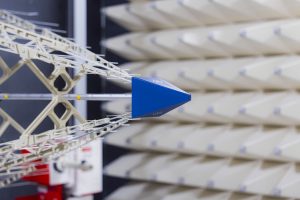
Test Site Requirements Radiated emissions are measured either at an Open Area Test Site (OATS) or at an approved alternative site — most commonly a semi-anechoic chamber (SAC) that’s been validated to deliver results equivalent to an OATS. The standard outlines site validation through normalized site attenuation (NSA) measurements. Stancer Testing-Lab’s semi-anechoic chambers meet ANSI C63.4 validation requirements.
Antenna Height Scanning During radiated emission testing, the receive antenna is swept vertically (generally between 1 m and 4 m above the ground plane) while the equipment under test (EUT) rotates a full 360°. Whatever peak emission is detected — at any angle or antenna height — gets recorded and checked against the relevant limit. This scanning process is designed to capture the worst-case emission geometry.
Detector Functions The standard calls for both quasi-peak (QP) and average (AVG) detectors, aligned with CISPR 16 receiver specifications. Under FCC Part 15 Subpart B, quasi-peak is the primary detector used across most frequency bands, although average limits also come into play for certain conducted emission ranges.
EUT Configuration and Operating Modes ANSI C63.4 specifies exactly how the EUT should be set up for testing — cable layouts, peripheral connections, and operating modes included. Testing must be conducted under whatever configuration generates the highest emissions, which means understanding the product’s internal clocking and data activity patterns is essential.
FCC Authorization Methods for Subpart B Devices
Devices tested under ANSI C63.4 can move forward through one of two FCC authorization paths:
FCC Certification
This route applies to specific Class B products, including personal computers, peripheral devices, and other designated equipment types. It involves submitting a test report showing ANSI C63.4 compliance to an FCC-authorized Telecommunications Certification Body (TCB). Stancer Testing-Lab provides accredited FCC testing and supports manufacturers through the equipment authorization process, including preparation of the technical documentation required for submission to an FCC-recognized Telecommunications Certification Body (TCB), where certification is required.
Supplier’s Declaration of Conformity (SDoC)
This path covers the majority of Class A devices, along with select Class B products like peripherals that don’t require formal certification. Under SDoC, the responsible party conducts testing according to ANSI C63.4 methods, applies the appropriate FCC label, and keeps test documentation on file. There’s no need to submit anything to a TCB, but records must be preserved and provided to the FCC upon request.
Combined US/Canada Testing
Many products need to satisfy compliance requirements for both the FCC (US) and Industry Canada / ISED (Canada). In many cases, ANSI C63.4 test data can support both FCC and ICES-003 compliance within a single combined test campaign saving both time and cost. Reach out to our engineering team to discuss combined testing strategies tailored to your product.